4 © 2001 Directed Electronics, Inc. Vista, CA
primary harness (H1), 12-pin connector
The primary harness plugs into the 12-pin socket of the control module.
______
______
______
______
______
______
______
______
______
______
______
______
H1/1 and H1/2 GRAY speaker outputs (2): Connect these wires to the speaker provided with the system.
IMPORTANT! If these wires are shorted to ground, the unit will be damaged.
H1/3 BLUE (-) hood/trunk input: This wire responds to a (-) input with an instant trigger, ideal for hood/trunk pins.
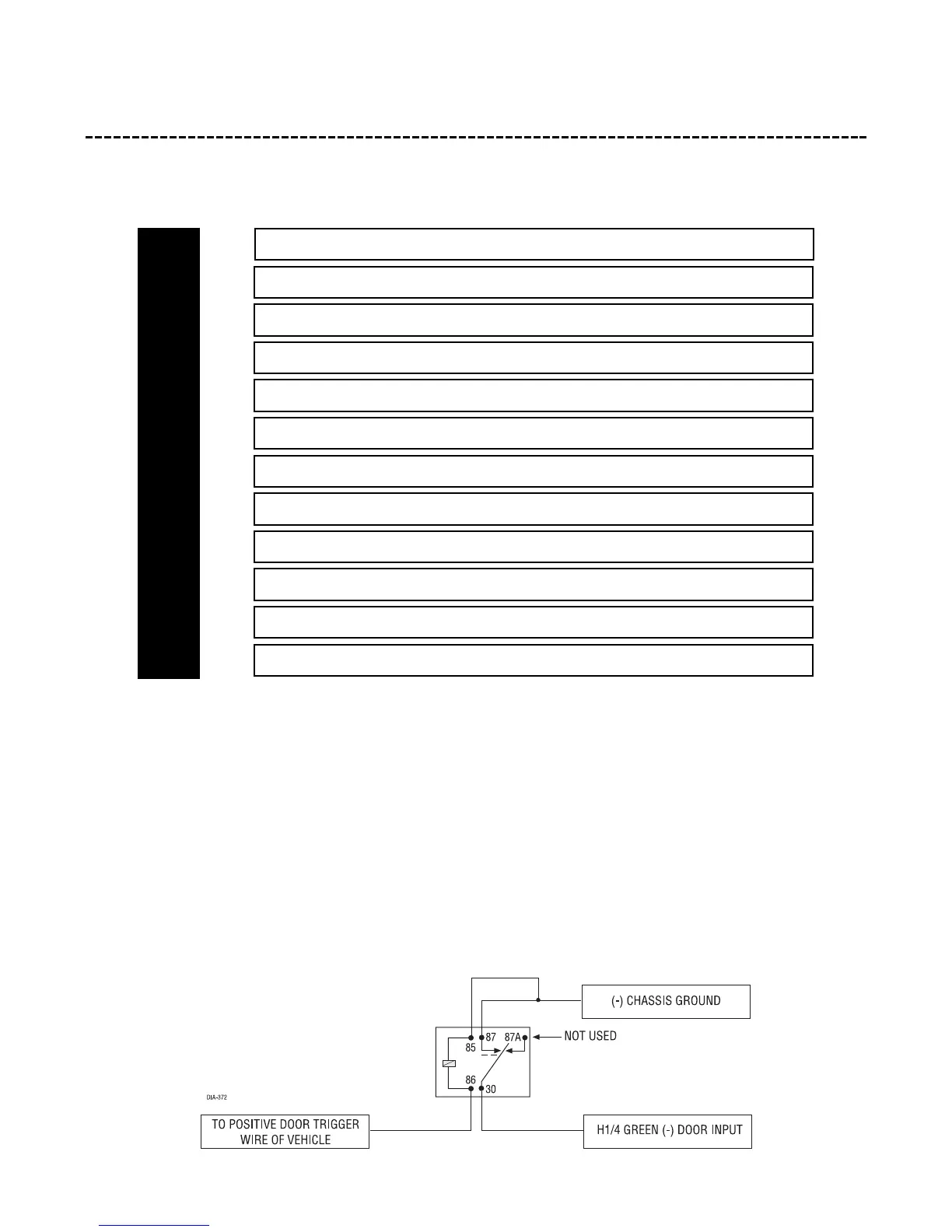
H1/4 GREEN (-) door trigger input: Most vehicles use negative door trigger circuits. Connect the green wire to
a wire that shows ground when any door is opened. In vehicles with factory delays on the domelight circuit, there
is usually a wire that is unaffected by the delay circuitry. For vehicles with a positive door trigger circuit, a relay
must be added as shown in the following diagram:
RED (+) 12V CONSTANT POWER INPUT
BLACK (-) CHASSIS GROUND INPUT
YELLOW (+) 12V IGNITION INPUT
ORANGE GROUND-WHEN-ARMED INPUT
BLUE/WHITE CUSTOM RECORDED MESSAGE 1 INPUT
RED/WHITE CUSTOM RECORDED MESSAGE 2 INPUT
BLACK/WHITE CUSTOM RECORDED MESSAGE 3 INPUT
BROWN OPTIONAL SIREN INPUT
GREEN (-) DOOR TRIGGER INPUT
BLUE (-) HOOD/TRUNK INPUT
GRAY SPEAKER OUTPUT
GRAY SPEAKER OUTPUT
H1/1
H1/2
H1/3
H1/4
H1/5
H1/6
H1/7
H1/8
H1/9
H1/10
H1/11
H1/12