6 © 2001 Directed Electronics, Inc. Vista, CA
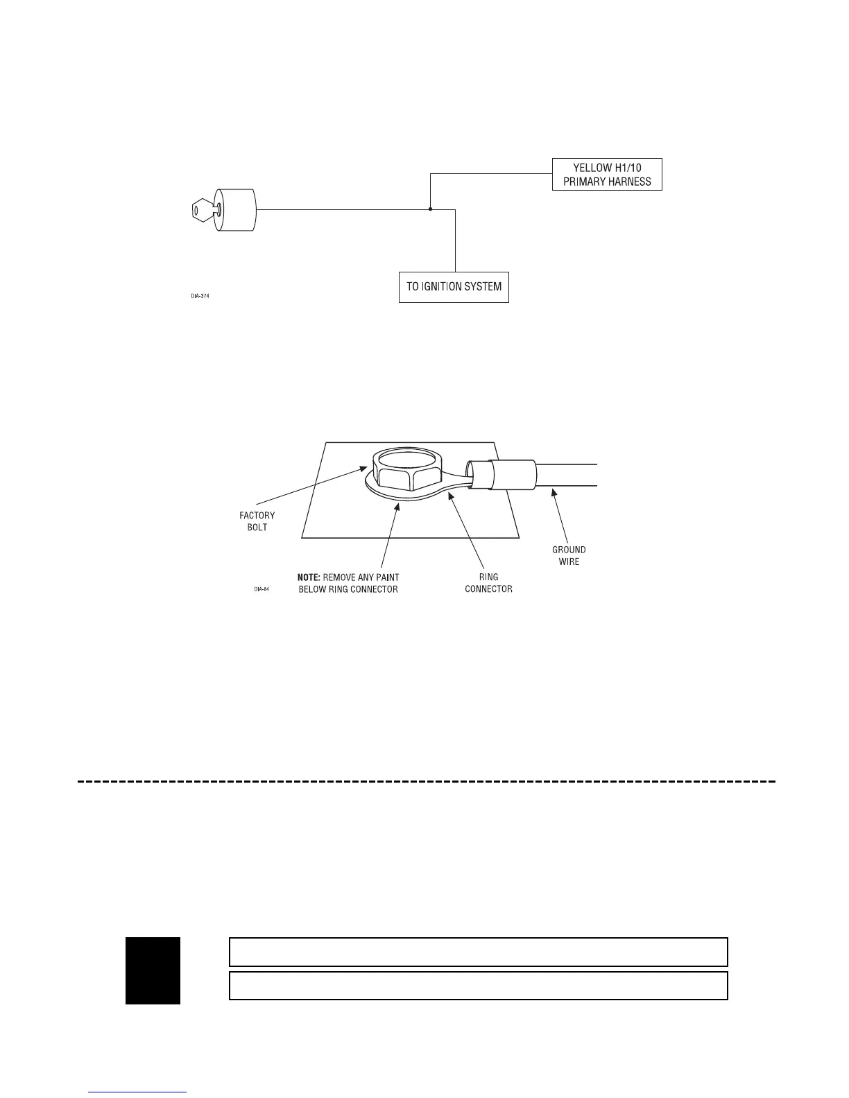
H1/10 YELLOW (+) 12V ignition input: The H1/10 YELLOW wire must be connected to the true (+)12V ignition
wire of the vehicle, whether the 516L is being interfaced with a security system or a remote start system.
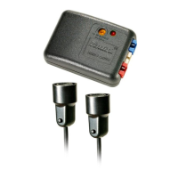
H1/11 BLACK (-) chassis ground input: Remove any paint and connect this wire to bare metal, preferably with
a factory bolt rather than your own screw. (Screws tend to either strip or loosen with time.) We recommend
grounding all your components, including the siren, to the same point in the vehicle.
H1/12 RED (+) constant power input: Connect this wire to the positive battery terminal or to the constant 12V
supply to the ignition switch.
NOTE: Always use a fuse within 12 inches of the point you obtain (+)12V.
remote start input harness (H2), 2-pin connector
This harness and its connections are only required when wiring the 516L to a remote start system. The remote
start input harness plugs into the red 2-pin socket on the control module. When interfaced with a remote start
system, the 516L detects various remote start states by monitoring the H1/10 YELLOW, H2/1 ORANGE/BLACK, and H2/2
BLUE/BLACK wires, and in different combinations of wire activation, the 516L emits the appropriate voice message.
______
______
BLUE/BLACK (-) STATUS/SECOND IGNITION INPUT (OPTIONAL)
ORANGE/BLACK (-) ACCESSORY INPUT (OPTIONAL)
H2/1
H2/2