16
© 2003 directed electronics, inc.
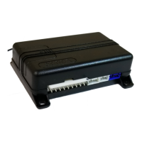
auxiliary harness wire connection guide
auxiliary harness wiring diagram
___
___
___
___
___
___
___
auxiliary harness wiring guide
H2/1 BROWN (-)horn honk output: This wire supplies a 200 mA (-) output that can
be used to honk the vehicle’s horn. It provides a pulsed output when the security sys-
tem is armed/disarmed and in the triggered sequence or in panic mode. In most vehi-
cle’s with (-) horn circuits this wire can control the vehicle’s horn without adding a
relay. If the vehicle has a (+) horn circuit, an optional relay must be used to interface
with the vehicle’s horn circuit.
IIMMPPOORRTTAANNTT!!
Never use this wire to drive anything but a relay or a low-current input!
This transistorized output can only supply (-) 200 mA, and connecting directly to a sole-
noid, motor, or other high-current device will cause the module to fail.
H2/2 GREEN no function.
H2/3 RED no function.
H2/4 BLUE no function.
H2/5 GRAY no function.
YELLOW/BLACK No Function
VIOLET/BLACK (-) 200mA Channel 4 Output
GRAY No Function
BLUE No Function
RED No Function
GREEN No Function
BROWN (-) Horn Honk Output
H2/1
H2/2
H2/3
H2/4
H2/5
H2/6
H2/7