+12V
GND
Fuse
D2D (4 pin, wht)
ESP (3 pin, blk)
ESP (4 pin, brn)
2 pin
4 pin
+12V
GND
D2D
(4 pin, white)
2 pin
4 pin
cut loop (see table)
✂
CPU1
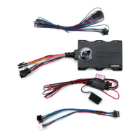
NOTE: The appearance and connector/port arrangement on the
Directed/Avital/Xpresskit system may dier to the examples shown .
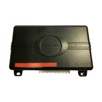
SmartStart Module
(Top view)
SmartStart Module to Xpresskit
Directed System
(Top view)
LED
Installation Procedure
This product is compatible with all Directed Electron-
ics Security, Remote Start and hybrid systems that are
ESP2 compatible (3 or 4-pin).
CAUTIONS
The white plug is ONLY for RSR (Remote Start
Ready) applications
For systems with combined 4-pin ESP/D2D ports,
you CANNOT use an interface module in D2D
mode when using a SmartStart module. You must
use W2W on the bypass module
There should NEVER be more than one data plug
connected from the 3-way harness
DO NOT cut any of the loops on the SmartStart
Module (unless used for RSR applications)
DO NOT connect the black 3-pin ESP connector to
white Door Lock port on Directed systems
Please read the following before proceeding
1. Customer Information required:
• Record the customer information requested
in step 5a of this procedure. The module ID
# is provided on a sticker which can be af-
fixed to the space provided in step 5a.
• Is this a new account or one being added to
an existing account? Check box(es) in 5a.
This information is required for final verifi-
cation/activation of the VSM200/250 or
DSM200/250.
2. Installation Points:
• Install and test the security/remote start sys-
tem first using the associated guides and
wiring diagram. If using an existing system,
verify it is fully functional before installing the
Directed SmartStart module.
• For 3000-series Remote Start systems with
no supplied remote control, test the installed
system using the functional commands in the
SmartStart activation portal.
• Mount the SmartStart module as high as pos-
sible in the vehicle (side with color label and
model number facing down). Mount with
minimal obstructions that can affect commu-
nications and within reach of the main Di-
rected system using the provided cables (do
not extend).
• DO NOT connect the SmartStart module un-
til the final programming of the Remote Start
main unit and verification of security/remote
start system operations are completed.
QRNDSM250 2011-05
Signal Strength (RSSI)
The module's signal strength (RSSI) can be viewed in the
activation portal after a successful transmission test. This field is
displayed on the webpage as "RSSI: XX dB" with XX being the
numeric variable. Use the range guide (at right) to determine
the signal strength. Monitor this signal during installation to
ensure the device is mounted in a location which maximizes
signal strength with minimal interference.
GPS location accuracy should also be checked on the activa-
tion portal when activating DSM/VSM250 modules.
Quick Reference
Install Guide
VSM200/250, DSM200/250
-50 to -90 dB
-91 to -100 dB
> -100 dB
= good signal strength
= borderline/inconsistent signal strength
= weak, insufficient signal strength
Wiring Schematic