Do you have a question about the Distech Controls EC-BOS-8 and is the answer not in the manual?
Shutter for microSD card access.
Internal component for holding the microSD card.
Card storing unit identity and data.
Steps for attaching the unit to a DIN rail.
How to install option modules onto the DIN rail.
Serial communication interface.
Wireless network connection.
Wired network connection.
Connection for power and earth ground.
Installation of earth ground wire.
Options for AC and DC power supply.
Description of status and activity LEDs.
Overview of USB ports and control switches.
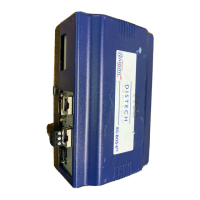
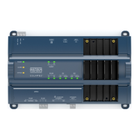
Details on the DIN-mount area controller.
List of items included in the package.
Required materials and tools for installation.
Procedure for inserting the microSD card.
Safety precautions for installation and servicing.
Recommendations for controller placement.
Operating conditions for the product.
Connecting RS485, WLAN, and Ethernet.
Connecting RS485 devices and network configuration.
Configuration of RS485 biasing and termination.
Connecting to primary and secondary Ethernet ports.
Grounding and power connection methods.
Finalizing earth ground and power wiring.
Steps for applying power and checking system status.
Understanding the controller's status LEDs.
Using USB ports for data and controls.
Alternative mounting method using tabs.
| Model | EC-BOS-8 |
|---|---|
| RS-485 Ports | 1 |
| Power Supply | 24 VAC/VDC |
| Enclosure Rating | IP20 |
| Controller Type | BACnet |
| Communication Protocols | BACnet/IP, BACnet MS/TP |
| Input/Output | 8 Inputs / 8 Outputs |
| Processor | ARM Cortex-A8 |
| Ethernet Ports | 1 (10/100 Mbps) |
| Input Types | 0-10 VDC, 4-20 mA, Resistive, Dry Contact |
| Mounting | DIN Rail |
| Type | Building Automation Controller |
| Relative Humidity | 5 to 95% RH, non-condensing |