9
EN
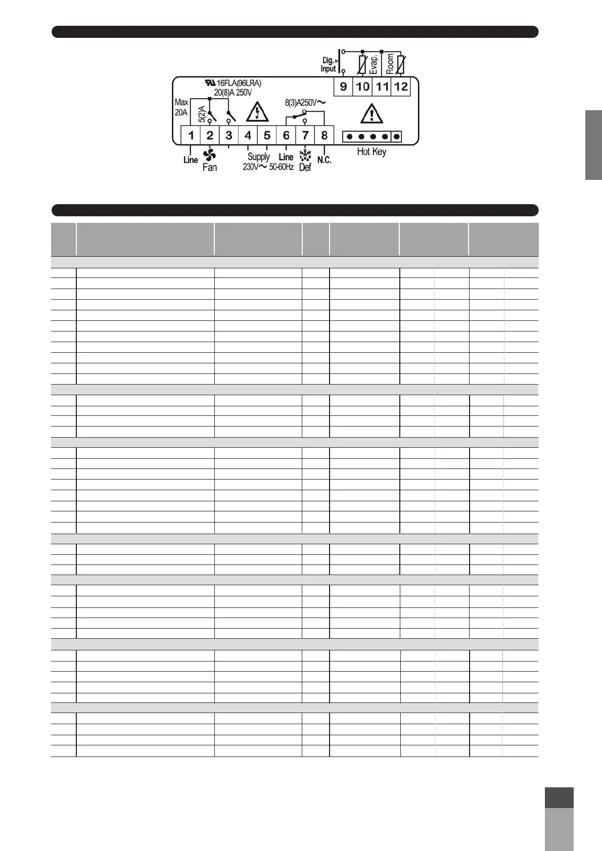
6. CONNECTIONS
7. STANDARD VALUES
Defrost Defrost Defrost
BY AIR BY HOT GAS BY HEATERS
Label Description Range level TA TN TB TN TB
REGULATION
SET Set point LS ÷ US L1 10 0 -22 0 -22
Hy Differential 0,1 ÷ 25°C/1 ÷ 45 °F L1 2 2 2 2 2
LS Minimum Set Point -55° C ÷ SET/67° F ÷ SET L2 5 -5 -25 -5 -25
US Maximum Set Point SET ÷ 99 °C/SET ÷ 210 °F L2 15 5 -18 5 -18
ot First probe calibration -10 ÷ +10 °C/-18 ÷ +18°F L1 0 0 0 0 0
P2 Second probe presence n ÷ Y L1 n y y y y
oE Second probe calibration -10 ÷ +10 °C/-18 ÷ +18°F L2 0 0 0 0 0
od Outputs activation delay at start up 0 ÷ 99 min L2 0 0 0 0 0
AC Anti-short cycle delay 0 ÷ 50 min L1 2 2 2 2 2
Cy Compressor ON time faulty probe 0 ÷ 99 min L2 0 0 0 0 0
Cn Compressor OFF time faulty probe 0 ÷ 99 min L2 0 0 0 0 0
DISPLAY
CF Measurement unit °C ÷ °F L2 °C °C °C °C °C
rE Resolution (only for °C) in ÷ dE L1 in in in in in
Ld Default Display P1 - P2 L2 P1 P1 P1 P1 P1
dy Display delay 0 ÷ 15 min L2 0 0 0 0 0
DEFROST
td Defrost type EL - in L1 EL In In EL EL
dE Defrost termination temperature
-55 ÷ +50 °C/-58 ÷ +122°F
L1 50 20 20 30 30
id Interval between defrost cycles 0 ÷ 99 hours L1 4 4 4 4 4
Md Maximum length for defrost 0 ÷ 99 min L1 20 20 20 30 30
dd Start defrost delay 0 ÷ 99 min L2 0 0 0 0 0
dF Display during defrost rt - it - SP - dE L2 rt rt rt rt rt
dt Drip time 0 ÷ 99 min L2 0 2 2 2 2
dP Defrost at power-on n - y L2 n n n n n
FANS
FC Fans operating mode cn - on - cY -oY L1 oY on on on on
Fd Fans delay after defrost 0 ÷ 99 min L1 0 3 3 3 3
FS Fans stop temperature
-55 ÷ +50 °C/-58 ÷ +122°F
L2 40 40 40 40 40
ALARMS
AA Temperature alarms configuration rE - Ab L2 rE rE rE rE rE
AU Maximum temperature alarm AL ÷ +99 °C/AL ÷ +210°F L1 5 5 5 5 5
AL Minimum temperature alarm -55,0 °C + AU/67 °F ÷ AU L1 5 5 5 5 5
Ad Temperature alarm delay 0 ÷ 99 min L2 0 0 0 0 0
dA Exclusion of temp. alarm at start up 0 ÷ 99 min L2 90 90 90 90 90
DIGITAL INPUT
iP Digital input polarity oP ÷ cL L1 oP oP oP oP oP
iF Digital input configuration EA-bA-do-dF-Au-hc L1 bA bA bA bA bA
di Digital input delay 0 ÷ 99 min L1 0 0 0 0 0
dC
Compressor and fan status with open door
no/Fn/cP/Fc L2 Fc Fc Fc Fc Fc
rd Regulation with door open n - y L2 y y y y y
OTHER
d1 Thermostat probe display Read Only L2 - - - - -
d2 Evaporator probe display Read Only L1 - - - - -
Pt Parameter code table Read Only L2 - - - - -
rL Firmware release Read Only L2 - - - - -
 Loading...