1592020080 XR72CX GB m&M r1.1 27.03.2015 XR72CX 4/4
14.2 OTHER MESSAGES
In programming mode: none parameter is present in Pr1
On the display or in dP2, dP3, dP4: the selected probe is nor enabled
15. TECHNICAL DATA
Housing: self extinguishing ABS.
Case: XR72CX frontal 32x74 mm; depth 60mm;
Mounting: XR72CX panel mounting in a 71x29mm panel cut-out
Protection: IP20; Frontal protection: XR72CX IP65
Connections: Screw terminal block 2,5 mm
2
wiring.
Power supply: according to the model: 12Vac/dc, ±10%; 24Vac/dc, ±10%; 230Vac 10%,
50/60Hz, 110Vac 10%, 50/60Hz
Power absorption: 3VA max
Display: 3 digits, red LED, 14,2 mm high; Inputs: Up to 4 NTC or PTC probes.
Digital input: free voltage contact
Relay outputs: compressor 1 SPST 8(3) A, 250Vac; SPST 16(6)A 250Vac
defrost: SPDT 8(3) A, 250Vac or SPST 16(6)A 250Vac
fan: SPST 5A, 250Vac or SPST 16(6)A 250Vac
compressor 2: SPDT 8(3) A, 250Vac or SPST 16(6)A 250Vac
Data storing: on the non-volatile memory (EEPROM).
Kind of action: 1B; Pollution grade: 2;Software class: A.;
Rated impulsive voltage: 2500V; Overvoltage Category: II
Operating temperature: 0÷60 °C;Storage temperature: -30÷85 °C.
Relative humidity: 2085% (no condensing)
Measuring and regulation range: NTC probe: -40÷110°C (-40÷230°F);
PTC probe: -50÷150°C (-58÷302°F)
Resolution: 0,1 °C or 1°C or 1 °F (selectable); Accuracy (ambient temp. 25°C): ±0,7 °C ±1 digit
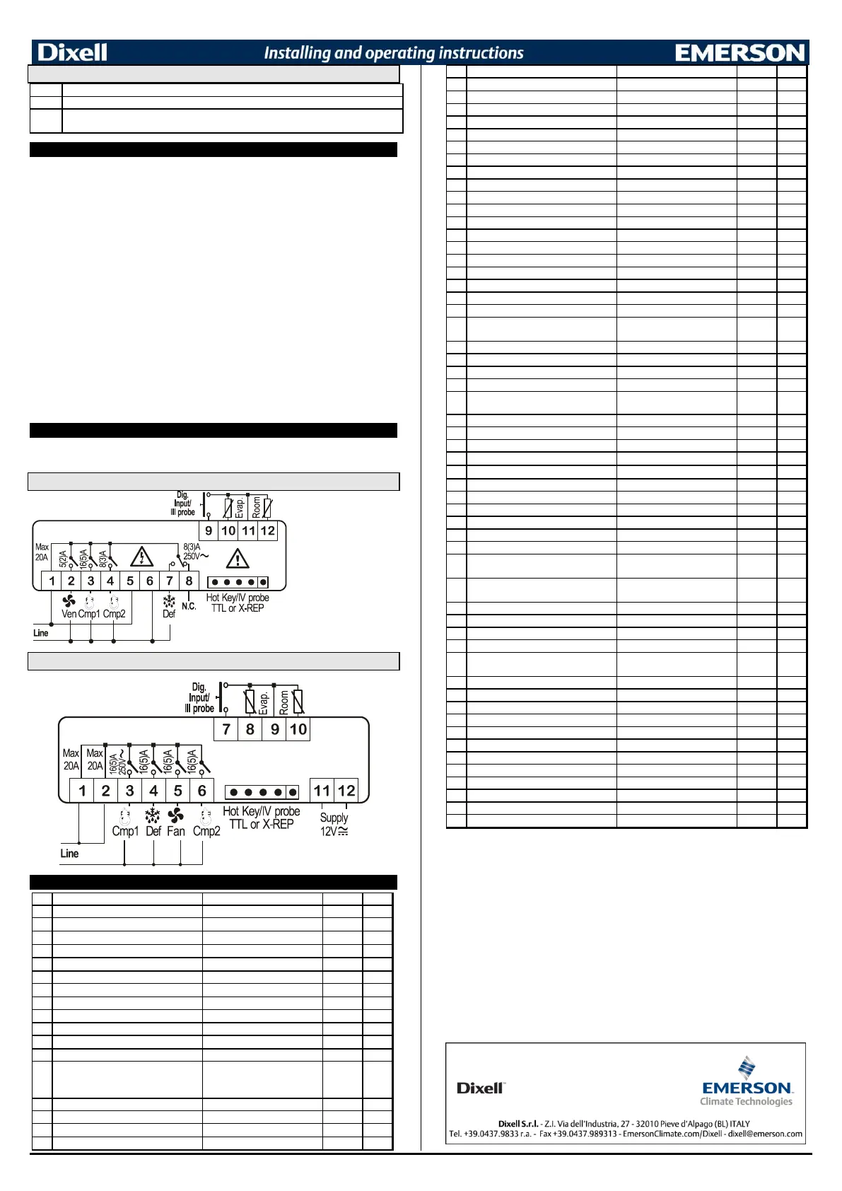
16. CONNECTIONS
The X-REP output excludes the TTL output.. It’s present in the following codes:
XR72CX- xx2xx, XR72CX –xx3xx;
16.1 XR72CX – 8A OR 16A COMP. RELAY - 230VAC OR 120VAC
NOTE: The compressor
relay is 8(3)A or 16(6)A
according to the model.
24Vac supply: connect
to the terminals 5 and 6.
16.2 XR72CX –4 X 16A - 12VAC/DC
17. DEFAULT SETTING VALUES
Thermostat probe calibration
Evaporator probe presence
Evaporator probe calibration
Outputs delay at start up
P1-P2 percentage for regulation
Set point for continuous cycle
(-55.0÷150,0°C) (-67÷302°F)
Compressor ON time with faulty probe
Compressor OFF time with faulty probe
Temperature measurement unit
in=integer; dE= dec.point
P1 - P2 - P3 - P4 - SEt - dtr
Display temperature delay
P1-P2 percentage for disply
EL=el. heater; in= hot gas
Probe selection for defrost termination
Defrost termination temperature
Interval between defrost cycles
(Maximum) length for defrost
Displaying during defrost
MAX display delay after defrost
First defrost after startup
Defrost delay after fast freezing
Differential of temperature for forced
activation of fans
Fan on time with compressor off
Fan off time with compressor off
Probe selection for fan management
Temperat. alarms configuration
rE= related to set;
Ab = absolute
MAXIMUM temperature alarm
Minimum temperature alarm
Differential for temperat. alarm recovery
(0,1°C÷25,5°C) (1°F÷45°F)
Delay of temperature alarm at start up
Probe for temperat. alarm of condenser
Condenser for low temperat. alarm
(-55 ÷ 150°C) (-67÷ 302°F)
Condenser for high temperat. alarm
(-55 ÷ 150°C) (-67÷ 302°F)
Differ. for condenser temp. alar. recovery
[0,1°C ÷ 25,5°C] [1°F ÷ 45°F]
Condenser temperature alarm delay
Delay of cond. temper. alarm at start up
Compr. off for condenser low
temperature alarm
Compr. off for condenser high
temperature alarm
Digital input configuration
EAL, bAL, PAL, dor; dEF; Htr, AUS
Digital input alarm delay
Number of activation of pressure switch
Compress and fan status when open
door
Regulation restart with door open alarm
Differential for Energy Saving
(-30°C÷30°C) (-54°F÷54°F)
2
Only for models XR72CX–xx2xx, XR72CX–xx3xx;
 Loading...