Do you have a question about the dixell xc440c and is the answer not in the manual?
Manual is part of product, keep for reference. Instrument not for safety. Check application limits.
Check voltage, avoid water/moisture, disconnect before maintenance, do not open, return faulty units, consider relay current, separate wires, fit probes safely, use filters if needed.
Sets temperature/pressure relation for specific gases. Pre-set is r404. Access via Pr2 parameter, password 3-2-1, then FtyP.
Configures pressure probe range using PA04 (4mA) and PA20 (20mA) parameters. Supports PP11 (-0.5÷11 bar) and PP30 (0÷30 bar) probes.
Selects display type for pressure (relative or absolute) after setting probe range. Access via Pr2 parameter, password 3-2-1, then rELP.
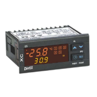
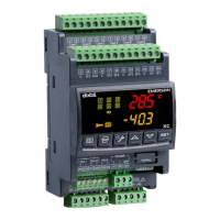
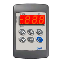
Details of the controller's display: upper display for temperature, lower for pressure, and icons for status, unit, and loads.
Explains functions of SET, UP, DOWN, and CLOCK keys. Includes key combinations for locking/unlocking keyboard and entering/exiting programming mode.
Details of LED indicators and their meanings, covering units (°C, °F, bar, PSI), load status (on, waiting, maintenance), and alarm states (maintenance, alarm happening, new alarm).
Shows how to view set points for compressors (SEtC) or fans (SEtF) by pressing the SET key. Exit by pressing SET again or waiting.
Guides on modifying set points. Recommends checking/setting freon type (FtyP) and measurement unit (dEU) first.
Explains how to access the user-accessible "Pr1" parameter list by holding SET and DOWN keys for 3 seconds, then using SET to navigate and modify values.
Details how to access the protected "Pr2" parameter list using the security code 321. Requires first entering the "Pr1" level.
Describes the procedure for changing parameter values: enter programming mode, select parameter, press SET to blink, use UP/DOWN to change, press SET to store.
Explains how to disable an output for maintenance by accessing the 'Sta' menu via the CLOCK key, selecting the output, and toggling its status between 'On' and 'oFF' using SET and UP/DOWN keys.
Indicates that a disabled output is signaled by its LED blinking at 2 Hz.
When outputs are disabled, they are excluded from regulation, and the system continues to operate with the remaining enabled outputs.
Details how to view the running hours of each load by pressing the CLOCK key, which displays 'Hur' and the hours on the respective displays.
Explains how to access and navigate the alarm menu to view alarm codes, numbers, and durations. Also covers how to erase displayed or all alarms.
Guides on programming a 'Hot Key' from the instrument via upload. Involves connecting the Hot Key when the controller is ON and following on-screen prompts.
Details programming an instrument using a 'Hot Key' via download. Connects the Hot Key to the instrument and powers it on to transfer parameters.
Explains how to lock the keyboard by pressing UP and DOWN keys simultaneously for over 3 seconds, displaying 'POF'.
Details how to unlock the keyboard by pressing UP and DOWN keys simultaneously for over 3 seconds, until 'POn' appears.
Configures plant size and regulation type using oA1-oA4 for outputs, CtyP for compressor type, and PC1-PC4 for compressor power. Supports compressors or fans only, not mixed.
Configures probe type (Pbc), read-out adjustments for 4mA (PA04) and 20mA (PA20) signals, and probe calibration (CAL) for Probe 1.
Configures polarity and functions for digital inputs (i1c, i1F), alarm input polarity (ALIP), and manual alarm reset (ALMr).
Defines minimum (LSE) and maximum (HSE) set points for compressors, dependent on the dEU measurement unit setting.
Configures proportional band (Pb), energy saving (ESF), time delays (Fon, FoF), and min/max set points (LSF, HSF) for fan regulation.
Defines fan alarms: low/high pressure (LAF, HAF), alarm delays (AFd), and number of fans with faulty probes (FPr).
Includes other settings: alarm relay silencing (tbA), keyboard ON/OFF enabling (OFF), compressor/fan addresses (Ad1, Ad2), software release (rEL), parameter table (Ptb), and protected menu access (Pr2).
Describes Dead Band regulation for compressors, using a neutral zone (Pbd) to maintain stable operation. Regulation starts when pressure/temperature exceeds zone limits.
Explains Proportional Band regulation for compressors/fans. Stages ON/OFF are proportional to input signal, balancing running hours. Safety times and delays apply.
Details probe connection procedures, emphasizing polarity for 4-20mA probes, avoiding short circuits, using shielded cables, and placing temperature probes away from air streams.
Explains integration with XJ500 system via TTL serial port using ModBus RTU. Notes the controller has two serial addresses (Ad1 for compressors, Ad2 for fans) which must be distinct.
Describes how alarms are signaled: via output relay, buzzer, display message, and logging. Refers to table in 18.3 for details.
Details the A12 Configuration alarm, triggered by incorrect settings in OA1-OA4 or CtyP parameters. Displays 'A12' and the specific error.
Details the P1 probe failure alarm, generated by a faulty probe. Recovery is automatic. Uses parameters SPr, PoPr, and FPr based on configuration.
Covers high/low pressure (temperature) alarms (HA, LA, HA2, LA2) for compressors and fans. Uses LAL, HAL, LAF, HAF parameters and tao, AFd for delay.
Provides a summary table of alarm codes, descriptions, causes, actions, and reset methods for various alarm conditions like probe failure, safeties, pressure, liquid level, and load maintenance.
| Brand | dixell |
|---|---|
| Model | xc440c |
| Category | Controller |
| Language | English |