1592020070 XR70CX GB m&M r1.3 08.05.2012.doc XR70CX 1/5
Digital controller with defrost and fan management
XR70CX
1. GENERAL WARNING __________________________________________________________ 1
2. GENERAL DESCRIPTION ______________________________________________________ 1
3. CONTROLLING LOADS ________________________________________________________ 1
4. FRONT PANEL COMMANDS ___________________________________________________ 1
5. MAX & MIN TEMPERATURE MEMORIZATION _____________________________________ 1
6. MAIN FUNCTIONS ____________________________________________________________ 2
7. PARAMETERS _______________________________________________________________ 2
8. DIGITAL INPUTS _____________________________________________________________ 3
9. TTL SERIAL LINE – FOR MONITORING SYSTEMS _________________________________ 3
10. X-REP OUTPUT – OPTIONAL___________________________________________________ 3
11. INSTALLATION AND MOUNTING ________________________________________________ 4
12. ELECTRICAL CONNECTIONS __________________________________________________ 4
13. USE THE HOT KEY ___________________________________________________________ 4
14. ALARM SIGNALS _____________________________________________________________ 4
15. TECHNICAL DATA ____________________________________________________________ 4
16. CONNECTIONS ______________________________________________________________ 4
17. DEFAULT SETTING VALUES ___________________________________________________ 4
1. GENERAL WARNING
1.1 PLEASE READ BEFORE USING THIS MANUAL
This manual is part of the product and should be kept near the instrument for easy and quick
reference.
The instrument shall not be used for purposes different from those described hereunder. It
cannot be used as a safety device.
Check the application limits before proceeding.
1.2 SAFETY PRECAUTIONS
Check the supply voltage is correct before connecting the instrument.
Do not expose to water or moisture: use the controller only within the operating limits avoiding
sudden temperature changes with high atmospheric humidity to prevent formation of
condensation
Warning: disconnect all electrical connections before any kind of maintenance.
Fit the probe where it is not accessible by the End User. The instrument must not be opened.
In case of failure or faulty operation send the instrument back to the distributor or to “Dixell S.r.l.”
(see address) with a detailed description of the fault.
Consider the maximum current which can be applied to each relay (see Technical Data).
Ensure that the wires for probes, loads and the power supply are separated and far enough
from each other, without crossing or intertwining.
In case of applications in industrial environments, the use of mains filters (our mod. FT1) in
parallel with inductive loads could be useful.
Dixell Srl reserves the right to change the composition of its products, even without notice,
ensuring the same and unchanged functionality.
2. GENERAL DESCRIPTION
Model XR70CX, format 32x74mm, is microprocessor based controller, suitable for applications on
medium or low temperature ventilated refrigerating units. It has four relay outputs to control
compressor, fan, and defrost, which can be either electrical or reverse cycle (hot gas). The last one
can be used as light, for alarm signalling or as auxiliary output. It is also provided with up to 4 NTC or
PTC probe inputs, the first one for temperature control, the second one, to be located onto the
evaporator, to control the defrost termination temperature and to managed the fan. The digital input
can operate as third temperature probe. The fourth one, to connect to the HOT KEY terminals, is
used to signal the condenser temperature alarm or to display another temperature.
The HOT-KEY output allows to connect the unit, by means of the external module XJ485-CX, to a
network line ModBUS-RTU compatible such as the dIXEL monitoring units of X-WEB family. It
allows to program the controller by means the HOT-KEY programming keyboard.
The instrument is fully configurable through special parameters that can be easily programmed
through the keyboard.
3. CONTROLLING LOADS
3.1 COMPRESSOR
The regulation is performed according to
the temperature measured by the
thermostat probe with a positive
differential from the set point: if the
temperature increases and reaches set
point plus differential the compressor is
started and then turned off when the
temperature reaches the set point value
again.
In case of fault in the thermostat probe the start and stop of the compressor are timed through
parameters Con and CoF.
3.2 DEFROST
Two defrost modes are available through the tdF parameter: defrost through electrical heater
(tdF=EL) and hot gas defrost (tdF=in).
Other parameters are used to control the interval between defrost cycles (idF), its maximum length
(MdF) and two defrost modes: timed or controlled by the evaporator’s probe (P2P).
At the end of defrost dripping time is started, its length is set in the Fdt parameter. With Fdt=0 the
dripping time is disabled.
3.3 CONTROL OF EVAPORATOR FANS
The fan control mode is selected by means of the FnC parameter:
FnC=C_n, fans will switch ON and OFF with the compressor and not run during defrost.
FnC=o_n, fans will run even if the compressor is off, and not run during defrost.
After defrost, there is a timed fan delay allowing for drip time, set by means of the Fnd parameter.
FnC=C_Y, fans will switch ON and OFF with the compressor and run during defrost.
FnC=o_Y, fans will run continuously also during defrost.
An additional parameter FSt provides the setting of temperature, detected by the evaporator probe,
above which the fans are always OFF. This is used to make sure circulation of air only if his
temperature is lower than set in FSt.
3.3.1 Forced activation of fans
This function managed by the FCt parameter is designed to avoid short cycles of fans, that could
happen when the controller is switched on or after a defrost, when the room air warms the evaporator.
How it works: if the temperature difference between evaporator probe and room probe is higher than
the FCt parameter value, fans will be switched on. With FCt=0 the function is disabled.
3.3.2 Cyclical activation of the fans with compressor off.
When FnC=C-n or C-Y (fans working in parallel with the compressor), by means of the Fon and FoF
parameters the fans can carry out on and off cycles even if the compressor is switched off. When the
compressor is stopped the fans go on working for the Fon time. With Fon=0 the fans remain always
off, also when the compressor is off.
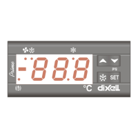
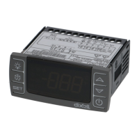
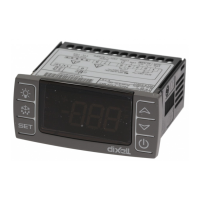
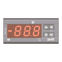
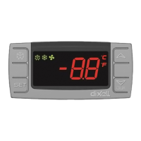
4. FRONT PANEL COMMANDS
To display target set point; in programming mode it selects a parameter or confirm
an operation.