EasyManua.ls Logo

dixell XR110C User Manual

dixell XR110C
4 pages
To Next Page IconTo Next Page
Page #1 background imageLoading...
Page #1 background image
Dixell
Installing and Operating Instructions
rel.1.0 - cod. 1592008200
1592008200 XR110C GB XR110C with built in RS485 1/4
XR110C with built-in RS485
CONTENTS
1. GENERAL WARNING _________________________________________________________________1
2. General description ___________________________________________________________________1
3. Controlling loads______________________________________________________________________ 1
4. Front panel commands_________________________________________________________________ 1
5. List of Parameters ____________________________________________________________________2
6. Digital inputs_________________________________________________________________________3
7. Installation and mounting_______________________________________________________________3
8. Electrical connections__________________________________________________________________ 3
9. RS485 Serial communication____________________________________________________________ 3
10. Use of the programming “HOT KEY “ _____________________________________________________ 3
11. Alarm signals ________________________________________________________________________ 3
12. Technical data _______________________________________________________________________4
13. Connections _________________________________________________________________________4
14. Default setting values__________________________________________________________________4
1. GENERAL WARNING
1.1 PLEASE READ BEFORE USING THIS MANUAL
This manual is part of the product and should be kept near the instrument for easy
and quick reference.
The instrument shall not be used for purposes different from those described
hereunder. It cannot be used as a safety device.
Check the application limits before proceeding.
1.2
SAFETY PRECAUTIONS
Check the supply voltage is correct before connecting the instrument.
Do not expose to water or moisture: use the controller only within the operating limits
avoiding sudden temperature changes with high atmospheric humidity to prevent
formation of condensation
Warning: disconnect all electrical connections before any kind of maintenance.
Fit the probe where it is not accessible by the End User. The instrument must not be
opened.
In case of failure or faulty operation send the instrument back to the distributor or to
“Dixell s.r.l.” (see address) with a detailed description of the fault.
Consider the maximum current which can be applied to each relay (see Technical
Data).
Ensure that the wires for probes, loads and the power supply are separated and far
enough from each other, without crossing or intertwining.
In case of applications in industrial environments, the use of mains filters (our mod.
FT1) in parallel with inductive loads could be useful.
2. GENERAL DESCRIPTION
XR110C is connectable to the XJ500 monitoring system through the two terminals of serial
port RS485.
Model XR110C, 32 x 74 mm format, is a single stage temperature controller suitable for
applications in the field of refrigeration or heating. It’s provided with a relay output and a
PTC or NTC probe inputs configurable by the User.
3. CONTROLLING LOADS
3.1 TYPE OF REGULATION
The regulation is performed according to the temperature measured by the probe.
The instruments are provided with the CH programmable parameter which enables the
user to set the regulation both for heating or cooling applications:
· CH = cL : cooling applications
· CH = Ht : heating applications
3.2 CH=CL : COOLING
The regulation is performed according to the temperature measured by the thermostat
probe with a positive differential from the set point: if the temperature increases and
reaches set point plus differential the compressor is started and then turned off when the
temperature reaches the set point value again.
3.3 CH = HT: HEATING
The Hy value is automatically set under the Set Point. If the temperature decreases and
reaches set point minus differential the regulation output is activated and then turned off
when the temperature reaches the set point value again.
N.B. :In case of fault in the thermostat probe the start and stop of the compressor are
timed through parameters “COn” and “COF”.
4. FRONT PANEL COMMANDS
:To display target set point; in programming mode it selects a parameter or
confirm an operation.
By holding it pressed for 5s the instrument Stand By started( If it is enable)
By holding it pressed for 3s when max or min temperature is displayed it will
be erased.
:To see the max. stored temperature; in programming mode it browses the
parameter codes or increases the displayed value. By holding it pressed for
3s the fast freezing cycle is started
:To see the min stored temperature; in programming mode it browses the
parameter codes or decreases the displayed value. By holding it pressed for
3s the auxiliary relay is switched ON or OFF ( If it is configured)
KEY COMBINATIONS:
+
To lock & unlock the keyboard.
+ To enter in programming mode.
+ To return to the room temperature display
.
4.1 USE OF LEDS
Each LED function is described in the following table.
LED MODE Function
ON Compressor enabled
FLASHING - Programming Phase (flashing with LED 1)
- Anti-short cycle delay enabled
LED1
FLASHING
Programming Phase (flashing with LED
)
ON - ALARM signal
- In “Pr2” indicates the parameter is also present in “Pr1”
4.2 HOW TO SEE THE MIN TEMPERATURE
1. Press and release the n key.
2. The “Lo” message will be displayed followed by the minimum
temperature recorded.
3. By pressing the n key or waiting for 5s the normal display will be
restored.
4.3 HOW TO SEE THE MAX TEMPERATURE
1. Press and release the o key.
2. The “Hi” message will be displayed followed by the maximum
temperature recorded.
3. By pressing the o key or waiting for 5s the normal display will be
restored.
4.4 HOW TO RESET THE MAX AND MIN TEMPERATURE RECORDED
To reset the stored temperature, when max or min temperature is displayed :
LED 1
Question and Answer IconNeed help?

Do you have a question about the dixell XR110C and is the answer not in the manual?

dixell XR110C Specifications

General IconGeneral
ModelXR110C
Power Supply12, 24Vac/dc ±10% or 115, 230Vac ±10% 50/60Hz depending on model
DisplayRed LED, 2 digits, 7.5mm high
Dimensions73.5x34.5x71 mm
Operating temperature0 ~ 60 °C
Storage temperature-30 ~ 85 °C
Input TypeNTC, PTC
Output TypeRelay
Temperature Range-50°C to 150°C
Measuring range-50°C to 150°C
Resolution0.1°C
Relative humidity20 ~ 85% RH (non-condensing)
Protection degreeIP20

Summary

General Warnings and Safety

Please Read Before Using This Manual

Manual is part of product; keep for reference; use only as intended; check limits.

Safety Precautions

Check supply voltage, avoid water/moisture, disconnect before maintenance, fit probe safely, contact distributor for faults.

Device Description and Control

General Description

XR110C is connectable to XJ500 monitoring system via RS485, suitable for refrigeration/heating with relay output.

Controlling Loads

Regulation based on measured temperature; CH parameter sets heating/cooling applications.

Cooling Regulation (CH=CL)

Cooling regulation with differential; compressor activates below setpoint-differential, stops at setpoint.

Heating Regulation (CH=HT)

Heating regulation with differential; compressor activates above setpoint+differential, stops at setpoint.

Front Panel Operation and Display

Front Panel Commands Overview

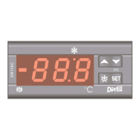
Description of SET, SET+HY, and SET+ keys for display, programming, and standby functions.

LED Indicators

Describes functions of LED 1 for compressor status, programming, and anti-short cycle delay.

Temperature Display and Reset

How to view and reset minimum and maximum stored temperatures using specific keys.

Advanced Operation and Parameters

Setpoint Adjustment

Instructions for viewing and changing the setpoint value using the SET and arrow keys.

Parameter List Access (PR1 and PR2)

Methods to enter user (PR1) and installer (PR2) parameter lists, including security code for PR2.

Parameter Value Modification

Procedure to change parameter values, including display, modification, and storage steps.

Keyboard Locking and Unlocking

How to lock the keyboard to prevent accidental changes and how to unlock it.

Standby Function

Enables/disables standby mode via SET key, switching off all relays and stopping regulation.

Parameter Categories

Lists parameters organized by function: Regulation, Display, Alarms, Probe Inputs, Digital Inputs.

Digital Inputs and Functions

Configurable Digital Inputs

Details on using digital inputs for generic alarm (EAL), serious alarm (BAL), pressure switch (PAL), and defrost (DFR).

Energy Saving and Remote Control

How digital inputs enable Energy Saving (ES) and Remote ON/OFF (ONF) functions.

Door Switch Functionality

Configuring door switch (DOR); its effect on outputs (odc) and alarm disabling.

Digital Input Polarity

Configuration of digital input polarity (CL/OP) and input function (I2F parameter).

Installation and Technical Specifications

Installation and Mounting

Instructions for panel mounting, environmental considerations, and ventilation.

Electrical Connections

Guidelines for connecting wires, power supply, probes, and outputs, including current limits.

Probe Connection

Recommendations for mounting the thermostat probe to ensure accurate temperature measurement.

RS485 Serial Communication

Information on connecting the unit via RS485 for ModBUS-RTU communication with monitoring systems.

Hot Key Operation

Procedures for downloading parameters to the instrument and uploading from the instrument to the Hot Key.

Alarm Signals and Messages

List of alarm messages (P1, HA, LA, EE, dA, EAL, BAL, PAL), their causes, and output behavior.

Alarm Recovery

How to recover from probe alarms (P1) and temperature alarms (HA, LA).

Technical Data

Specifications including housing, dimensions, protection, connections, power supply, display, and inputs.

Connections Diagrams

Wiring diagrams for XR110C models with different power supplies and compressor ratings.

Default Settings

Default Setting Values

Table showing default values for Regulation parameters like Set point and Differential.

Related product manuals