Dixie Chopper • 6302 E. County Road 100 N. • Coatesville, IN • 46121 • www.dixiechopper.com
Steering Linkage Adjustment
1. Place steering speed control levers in the neu-
tral lock position.
2. Chock front tires.
3. Jack up mower enough so that back tires
are off the ground. Use a jack with a suffi cient
safe working load capacity of at least 1/2 ton.
There are two drive belts that can need periodic adjust-
ment: the drive belt from the engine to the pumps, and
the drive belt from the engine to the mower deck.
These belts may be adjusted as follows:
1. Gain access to the underside of mower.
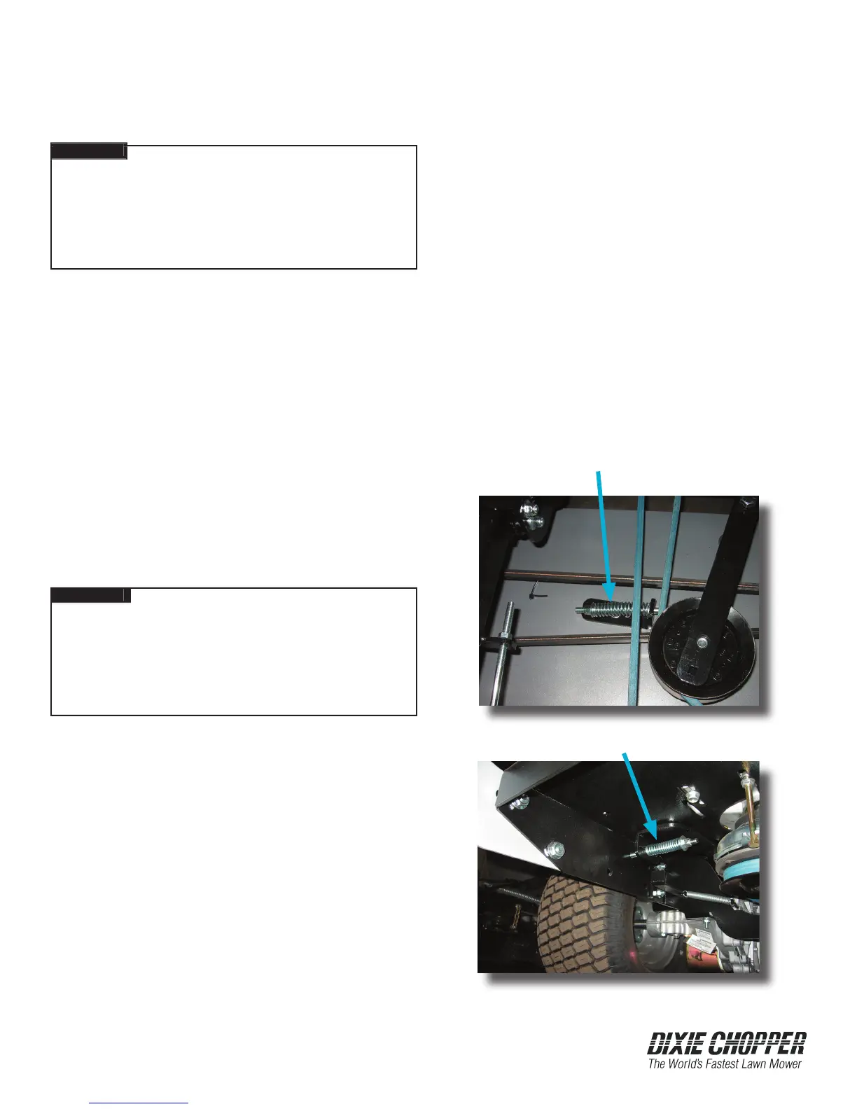
2. Adjust the drive belt from engine to pump at
the spring tensioner located near the left rear
wheel. Tighten the jamnut until spring mea-
sures 3 inches.
3. Adjust the drive belt from engine to mower
deck at the spring tensioner located at the back
of the mower deck. Tighten the jamnut until
spring measures 3 inches.
Drive Belt Replacement
Never attempt to make any
adjustments to mower deck or work under it while
mower is running. Make sure that ignition switch
is off and key removed, PTO switch is disengaged,
steering speed control levers are in neutral lock,
and parking brake is on. Failure to comply will re-
sult in personal injury or death.
Never attempt to make any
Never attempt to make any
adjustments to mower deck or work under it while
mower is running. Make sure that ignition switch
is off and key removed, PTO switch is disengaged,
steering speed control levers are in neutral lock,
and parking brake is on. Failure to comply will re-
sult in personal injury or death.
Replace the drive belts if they show signs of cuts,
tears, burns caused by slipping, or excessive wear.
Refer to the Routine Maintenance section of
this manual for a schedule of replacement.
Drive Belt Adjustment
Never attempt to make any
Never attempt to make any
DANGER
Never attempt to make any
Never attempt to make any
Never attempt to make any
Never attempt to make any
Never attempt to make any
Never attempt to make any
DANGER
Never attempt to make any
Never attempt to make any
Never attempt to make any
Never attempt to make any
4. With the motor running, loosen steering linkage
jamnut.
5. Loosen the two bolts.
6. Adjust control arm until wheel stops
turning.
7. Tighten the two bolts on steering linkage to
align with the hole in the pump control arm.
8. Remove wheel chocks.
9. Lower mower from jack.
1. Gain access to underside of mower.
2. Loosen the tension on the vertical/ horizontal
idler pulley by pulling it away from belt.
3. Roll belt off the pulley, noting the routing of belt.
4. Roll new belt onto pulley, routing it in the
same confi guration as belt just removed.
Manipulate pulley as needed.
Engine to Pump Tensioner Spring
Engine to Deck Tensioner Spring