Do you have a question about the dji Naza and is the answer not in the manual?
Compares different Naza control modes (GPS Atti., Atti., Manual) and their features.
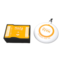
Describes the main controller, the brain of the system, including its IMU components.
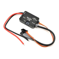
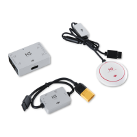
Explains the VU's role in power management, LED indication, and USB configuration.
Details the GPS/Compass module for sensing the position and direction.
Describes the bracket used for mounting the GPS module to minimize interference.
Explains the USB cable for connecting the MC to a PC for configuration and firmware updates.
Specifies the cables used for connecting the MC to the RC receiver.
Details the use of 3M gummed paper for fixing Naza components onto the multi-rotor frame.
Details example connections for the RC system, including receiver and channel setup.
Provides mounting and usage guidelines for the Versatile Unit, ensuring airflow and visibility.
Recommends specific ESCs/motors and details connection methods and refresh frequency.
Offers mounting and placement instructions for the GPS/Compass module to avoid interference.
Provides guidelines for mounting the Main Controller parallel to the aircraft horizon.
Outlines the essential steps for installing the assistant software and necessary drivers.
Provides an overview of the Assistant Software Graphical User Interface and its main sections.
Details on mounting the Naza MC and GPS module, emphasizing center of gravity and orientation.
Guide to selecting the correct mixer type for various multi-rotor configurations.
Instructions for adjusting the motor idle speed for optimal motor spool-up and performance.
Selecting the correct receiver type (Tradition, D-Bus, PPM) for transmitter communication.
Choosing between Immediately and Intelligent motor stop modes for safe operation.
Details on how to start the motors using Combination Stick Commands (CSC).
Explains the Immediately and Intelligent modes for stopping motors safely.
Calibrating the transmitter sticks to ensure accurate control inputs for the autopilot.
Optional step for remote gain tuning and gimbal pitch control setup.
Setting up control modes (Manual, Atti., GPS Atti.) using transmitter switch assignments.
Tuning basic gain parameters (Pitch, Roll, Yaw, Vertical) for optimal flight stability.
Configuring enhanced failsafe behaviors for scenarios like loss of transmitter signal.
Using IOC for enhanced flight control, allowing flight independent of the multi-rotor's nose direction.
Instructions on how to use the Course Lock feature for maintaining a consistent flight direction.
Instructions on how to use the Home Lock feature for returning the multi-rotor to a recorded home point.
Enabling and configuring the gimbal system, including output frequency selection.
Setting servo travel limits for Pitch and Roll to avoid mechanical binding and ensure correct angle.
Adjusting the automatic control gain for gimbal movement and feedback control direction.
Setting the manual control speed for gimbal pitch direction using a transmitter knob.
Enabling and configuring the two levels of low voltage protection for safe operation.
Setting up the battery type and calibrating voltage readings for accurate monitoring.
Configuring the first level of low voltage protection, including no-load and loss voltages.
Configuring the second level of low voltage protection and its associated warning actions.
Procedure for calibrating the digital compass to ensure accurate heading readings.
Crucial pre-flight checks and safety precautions for assembly and configuration.
Step-by-step guide for performing a safe and effective initial test flight.
Essential precautions and tips for successful multi-rotor flights when using GPS.
Troubleshooting the Toilet Bowl Effect by re-mounting the GPS module and recalibrating.
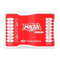
Detailed description of each port on the Main Controller for various functions.
Description of the ports available on the Versatile Unit for connectivity.
Details the connection port for the optional GPS & Compass module.
LED indicators for different GPS satellite counts and attitude status during flight.
LED indicators for Manual, Atti., and GPS Atti. control modes and stick positions.
LED indicators showing the status of compass calibration and potential errors.
LED indicators for Tx signal, voltage, PC connection, and system start/self-check status.
Overview of general built-in functions like autopilot modes and protection features.
Details on supported multi-rotors, ESC output, and recommended transmitter specifications.
Specifications for working voltage range, power consumption, operating temperature, weight, and dimensions.
Key flight performance metrics including hovering accuracy, angular velocity, and ascent/descent speed.
| Supported ESC Output | 400Hz |
|---|---|
| Operating Voltage Range | 4.8V~5.5V |
| Operating Temperature | -10°C ~ +50°C |
| Assistant Software System Requirement | Windows XP / Windows 7 / Windows 8 |
| GPS Accuracy | 2.5m (Horizontal) |
| Supported Flight Modes | Manual Mode, Attitude Mode, GPS Attitude Mode, Intelligent Orientation Control (IOC), Failsafe Mode |
| Supported Multi-Rotor Types | Quad-rotor I4, X4; Hex-rotor I6, X6; Octo-rotor I8, X8 |