EasyManua.ls Logo

DKS 1837 Series - User Manual

DKS 1837 Series
70 pages
Print Icon
To Next Page IconTo Next Page
Loading...
UL Listed
Copyright 2009 DoorKing, Inc. All rights reserved.
Copyright 2014 DoorKing, Inc. All rights reserved.
Date Installed:
Installer/Company Name:
Phone Number:
Leave Manual with Owner
Circuit Board
Serial Number
and Revision Letter:
Model Number
Installation/Owner’s Manual
PC Programmable
Telephone Entry and Access Control Systems
PC Programmable
PC Programmable
1833-084
1833-080
7
8
9
4
5
6
1
2
3
0
O
P
E
R
O
P
ER
W
X
YZ
W
X
Y
Z
T
U
V
T
U
V
P
Q
R
S
P
Q
R
S
M
N
O
M
N
O
JK
L
J
KL
G
H
I
G
H
I
D
E
F
D
E
F
A
B
C
A
B
C
S
P
S
P
TEL
EP
HONE
ENTR
Y
SYSTEM
O
PE
RA
TIN
G IN
S
TR
U
CT
I
O
N
S
Locate C
ode
N
umber
on Direc
to
r
y.
P
re
s
s
C
ode
Nu
m
ber
.
If Line is
B
usy,
P
re
s
s
“#
to
H
ang
UP
.
T
r
y
Again.
Ent
e
r on Ton
e
.
1.
2.
3.
7
8
9
4
5
6
1 2
3
0
O
P
E
R
O
P
E
R
W
X
Y
Z
W
X
Y
Z
T
U
V
T
U
V
P
Q
R
S
P
Q
R
S
M
N
O
M
N
O
J
K
L
J
K
L
G
H
I
G
H
I
D
EF
D
EF
A
B
C
AB
C
S
P
SP
TELEPHONE
ENTR
Y S
YSTEM
OPE
R
ATI
N
G INST
R
U
CTI
O
N
S
Locate
C
ode
N
umber
on
D
irec
to
r
y.
Pr
es
s
C
ode
N
u
m
ber
.
If Line
is
B
us
y,
Pr
es
s
“#”
to
H
ang
UP
.
T
r
y
Again.
Ent
e
r on To
n
e
.
1.
2.
3.
Flush Mount
Surface Mount
1833
1833
1833
Wall Mount
7 8
9
4
5
6
1
2
3
0
O
PE
R
O
P
E
R
WXYZ
W
X
Y
Z
TU
V
TU
V
PQ
RS
P
Q
R
S
M
N
O
M
N
O
JK
L
J
K
L
G
H
I
G
H
I
D
EF
D
EF
ABC
A
B
C
SP
S
P
A
Z
CALL
Flush Mount
1837-089
1837-084
1837-080
7
8
9
4
5
6
1
2
3
0
O
PE
R
O
P
E
R
WX
Y
Z
W
X
Y
Z
T
U
V
T
U
V
P
Q
R
S
P
Q
R
S
M
N
O
M
N
O
J
K
L
J
K
L
G
H
I
G
H
I
D
EF
D
EF
A
B
C
A
B
C
S
P
S
P
A
Z
CALL
A
Z
CALL
7
8
9
4
5
6
1
2
3
0
O
P
E
R
O
P
E
R
WX
Y
Z
W
X
Y
Z
T
U
V
T
U
V
P
Q
R
S
P
Q
R
S
M
N
O
M
N
O
J
K
L
J
K
L
G
H
I
G
H
I
D
EF
D
E
F
A
B
C
A
B
C
S
P
S
P
Surface Mount
1837
1837
1837
7
8
9
4
5
6
1
2
3
0
O
PE
R
O
P
E
R
WXYZ
W
X
Y
Z
TU
V
TU
V
PQRS
P
Q
R
S
M
NO
M
N
O
JK
L
JK
L
GH
I
G
H
I
D
EF
D
EF
AB
C
A
B
C
SP
S
P
A
Z
CALL
1835-089
1835-084
1835-080
7
8
9
4
5
6
1
2
3
0
O
P
ER
O
P
E
R
WX
YZ
W
X
YZ
T
U
V
T
U
V
P
Q
RS
PQ
R
S
M
N
O
M
N
O
JK
L
J
K
L
G
H
I
G
H
I
D
E
F
D
E
F
A
B
C
A
B
C
S
P
S
P
A
Z
CALL
TEL
EP
HONE EN
T
RY
S
YSTEM
HOLD TO
S
CAN
OP
ERA
T
IN
G IN
S
TR
U
CTIO
N
S
U
se “A
t
o Z”
Bu
t
t
on
s
to
Lo
c
at
e
N
ame
and
C
od
e
Nu
mb
er
on
Disp
la
y
.
N
am
e
s
a
re
In
Alp
ha
b
e
tic
a
l
Or
d
e
r
.
To
C
al
l
, En
t
er C
o
de Number
on
Ke
y
p
ad
o
r
Pr
es
s
C
a
ll
B
u
tto
n
.
If
Lin
e
is
B
u
sy
,
P
re
ss
#
or
“C
all
to
H
a
ng Up. Try
A
gai
n.
Enter
o
n
Ope
n
Disp
la
y
an
d
To
n
e
.
1
.
2.
3
.
A
Z
CALL
7
8
9
4
5
6
1
2
3
0
O
P
ER
O
P
E
R
WX
Y
Z
W
X
Y
Z
TU
V
T
U
V
P
Q
RS
PQ
R
S
M
N
O
M
N
O
JK
L
JK
L
G
H
I
G
H
I
D
E
F
D
E
F
A
B
C
A
B
C
S
P
S
P
TELEPHONE ENTR
Y SYS
T
EM
HOLD TO SCAN
O
P
ERAT
IN
G
I
NSTR
U
C
TI
O
N
S
Use
“A
to
Z” Button
s
to Lo
c
a
te
N
ame
a
n
d
C
o
d
e
Nu
m
be
r
o
n
D
i
s
pla
y
.
Nam
e
s a
re
I
n
Alp
ha
b
et
i
ca
l
O
r
d
er
.
T
o
C
al
l
,
En
t
er C
ode
N
u
mber on
Key
p
ad
o
r
Pr
e
s
s
C
a
l
l”
B
u
tto
n.
If
L
in
e
i
s
B
u
sy
,
P
r
e
s
s
#
o
r
C
a
l
l”
to
H
ang U
p.
Try Agai
n.
E
n
te
r
o
n
Op
en
D
is
play
a
n
d
T
o
ne
.
1.
2.
3.
Flush Mount
Surface Mount
1835
1835
1835
Wall Mount
26, 30 and 31-Bit Wiegand Compatable
1835-065-J-7-14

Table of Contents

Question and Answer IconNeed help?

Do you have a question about the DKS 1837 Series and is the answer not in the manual?

Summary

SPECIFICATIONS

Features

Details the key capabilities and functionalities of the system.

Important Notices

FCC - United States

Details FCC rules and regulations for the equipment.

DOC - Canada

Outlines Canadian Department of Communications certification and requirements.

Notice:

Explains load number assignment and transformer requirements.

Listing:

States compliance with UL 294 safety standards and ETL listing.

General Information

ADA mounting requirements for door control

Specifies ADA guidelines for mounting height for door controls.

SECTION 1 - INSTALLATION

1.1 General Installation

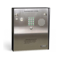
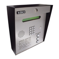
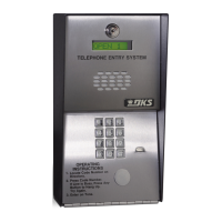
Describes the general installation steps and considerations for different mounting styles.

1.1.1 Remove Components from Enclosure

Details the procedure for safely removing system components from the enclosure.

1.1.2 Install Enclosure

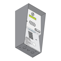
Explains how to mount the system enclosure in various configurations.

1.2 Surface Mount Dimensions

1.2.1 Surface Mount Recess Kit Dimensions and Installation

Details the installation and dimensions for the optional recess kit for surface mount units.

1.3 Flush Mount Dimensions

1.3.1 Flush Mount Kit Dimensions and Installation

Details the installation and dimensions for the flush mount kit.

1.3.2 Flush Mount Surface Mounting Kit Dimensions and Installation

Details the installation and dimensions for the flush mount surface mounting kit.

1.4 Wall Mount Dimensions

1.5 Memory Chip Replacement

1.6 Postal Lock Installation

SECTION 2 - WIRING

2.1 Wiring Guidelines

General guidelines for wiring, including power, wire runs, and grounding.

2.1.1 Power

Specifies power requirements and transformer usage for the system.

2.1.2 Wire Runs

Details best practices for routing wires and conduit.

2.1.3 Grounding

Explains the importance and methods for proper system grounding.

2.1.4 Surge Suppression

Recommends surge suppressors to protect the system from power surges.

2.1.5 Expansion Boards and Elevator Control

Refers to separate manuals for wiring expansion boards and elevator controls.

2.1.6 Ferrite Filter

Explains the use of ferrite filters to prevent noise and hum.

2.2 Terminal Descriptions

Identifies and describes the function of each terminal on the circuit board.

2.3 Telephone Entry System Wiring

Provides wiring diagrams for connecting the system components.

2.3.1 ALL Telephone Entry Systems - NO Tracker Expansion Boards

Shows wiring for systems without tracker expansion boards.

2.3.2 Tracker Expansion Boards (Hardwired)

Details wiring for hardwired expansion boards to increase entry points.

2.3.3 Tracker Expansion Boards using Wireless Communication

Explains wireless communication setup for expansion boards.

2.4 PC Connection Options

Outlines various methods for connecting the system to a PC for programming.

2.4.1 Phone Modem Connection

Describes connecting the system via a phone modem.

2.4.2 Direct Connection using RS-232 Terminal

Details connecting directly to the PC using an RS-232 cable.

2.4.3 RS-232 Terminal using RS-422;USB Connection

Explains connecting via RS-422/USB adapters.

2.4.4 RS-232 Terminal using Wireless or TCP;IP Connection

Describes wireless and TCP/IP connections using converters.

2.4.7 DoorKing DKS Internet-Modem Server

Describes connecting via the DKS Internet-Modem Server.

SECTION 3 - PROGRAMMING

3.1 General Programming Information

Provides general information about system programming methods and relays.

3.1.1 Programming from a PC

Details prerequisites and methods for PC programming.

3.1.2 Programming from the Telephone Entry System Keypad

Guides on programming using the system's keypad.

3.1.3 System Memory Chip Identification

Helps identify memory chip capacity and type for system programming.

3.2 Set-up Telephone Entry System for PC Programming

Steps for preparing the system for PC programming.

3.2.1 Master Code

Instructions for setting the system's master code, essential for programming.

3.2.2 Number of Area Codes Allowed

Configures the system to allow 10 or 255 area codes.

3.2.3 Call-up Operation when Interfacing with DoorKing 1816 or 1820 Systems Only

Special feature for interfacing with specific DoorKing intercom systems.

3.2.4 Resident Elevator Button Relay Time

Sets the duration for elevator access activation.

3.2.5 “Tone Open” Sound On or Off

Controls whether a tone sounds when a relay activates.

3.2.6 RS-232 Speed Setting

Adjusts the RS-232 communication speed.

3.2.7 Switch Input Feature

Configures how the switch input activates relays or dials numbers.

3.2.8 Elevator Control Feature

Enables or disables elevator access based on security levels.

3.2.9 Single or Multiple Systems

Sets the system to operate as single or part of a multi-system setup.

Overview for System Keypad Programming

Provides a summary table of keypad programming functions.

3.3 General Programming Using the System Keypad

Guides on general programming tasks using the system's keypad.

3.3.1 Relay Strike Time

Sets the activation duration for relays 0, 1, and 2.

3.3.2 Talk Time

Configures the maximum call duration for conversations.

3.3.3 Tone Open Numbers

Assigns functions to specific tone open numbers for relay activation.

3.3.4 Switch Input Relay(s) Activation

Determines which relays activate based on switch input.

3.3.5 Touch-Tone; Rotary-Dial

Sets the dialing format for outgoing calls (touch-tone or rotary).

3.3.6 Rotary-Dial 9 Relay(s) Activation

Configures relays activated by a rotary-dial 9 command.

3.4 Programming Letters, Numbers and Messages

Instructions for programming display messages and directory entries.

3.4.1 Programming Letters and Numbers from Keypad

Details how to input characters using the system keypad.

3.4.2 Programming the User Message - 1835 System

Guides on programming the user-specific message for the 1835 model.

3.4.3 Programming the Instruction Message - 1835 System

Guides on programming the system's instruction message for the 1835 model.

3.4.4 Programming the User Message - 1837 System

Guides on programming the user-specific message for the 1837 model.

3.4.5 Programming the Instruction Message - 1837 System

Guides on programming the system's instruction message for the 1837 model.

3.5 Programming Phone Numbers and Names

Covers entering resident phone numbers, names, and directory codes.

3.5.1 Programming the Directory Code Length

Sets the length (1-4 digits) for directory codes.

3.5.2 Programming Directory Codes with 7-Digit Phone Numbers - NO Area Code

Enters directory codes and 7-digit phone numbers without area codes.

3.5.3 Programming Area Codes

Adds area codes for long distance or 10-digit dialing.

3.5.4 Programming Directory Codes with Phone Numbers that use Area Codes

Enters directory codes with phone numbers that include area codes.

3.5.5 Programming Names - 1835 and 1837 Systems Only

Enters resident names into the directory for 1835 and 1837 systems.

3.5.6 Deleting Individual Phone Numbers

Removes a specific phone number linked to a directory code.

3.5.7 Delete Names - 1834, 1835 and 1837 Systems Only

Deletes resident names from the directory.

3.5.8 Delete Area Codes

Removes programmed area codes from the system.

3.5.9 Display Phone Numbers - 1835 and 1837 Systems Only

Views phone numbers associated with directory codes.

3.5.10 PBX Line Access Code Programming

Sets a line access code for PBX systems.

3.5.11 Touch-Tone Dialing Pause

Configures pause duration during touch-tone dialing.

3.6 Programming Device Codes - 1833, 1835, 1837 Only

Enters device codes for access control devices.

3.6.1 Programming Five-Digit Device Codes

Enters five-digit device codes for readers or transmitters.

3.6.2 Deleting Device Codes

Removes programmed device codes.

3.6.3 Enabling Facility Codes

Allows or disallows the use of facility codes.

3.6.4 Programming Facility Codes

Enters facility codes for device access.

3.7 Programming Four-Digit Entry Codes

Enters four-digit entry codes for resident access.

3.7.1 Programming Four-Digit Entry Codes

Details how to input four-digit entry codes.

3.7.2 Delete Entry Codes

Removes programmed four-digit entry codes.

3.7.3 Entry Code Ranges

Sets entry code ranges to activate specific relays.

3.8 Anti-Pass Back

Configures the Anti-Pass Back (APB) feature for access control.

3.8.1 Programming the Anti-Pass Back Mode

Selects the APB operation mode (Passive, Active, Trap).

3.8.2 Re-Sync All Devices

Resynchronizes all devices for proper APB operation.

3.8.3 Re-Sync Individual Devices

Resynchronizes a single device.

3.8.4 Reset Facility Counter

Resets the facility counter used in APB mode.

SECTION 4 - ADJUSTMENTS

1830 Series Circuit Board

Identifies adjustable components on the main circuit board.

4.1 Speaker Volume, Microphone and Feedback

Adjusts audio levels for optimal performance and feedback reduction.

4.2 Click Sensitivity - Use for Rotary-Dial Phones ONLY

Adjusts sensitivity for rotary-dial phone input.

4.3 LCD Display Contrast - 1835 and 1837

Adjusts the contrast of the LCD display on 1835 and 1837 models.

4.4 Backlite Cutoff

Notes that this adjustment is factory set and should not be altered.

4.5 Master Code Switch

Explains the function and operation of the master code switch.

4.6 Ring Pin Jumper

Details the function of the ring pin jumper for call answering.

4.7 Relay 2 Jumper

Describes the jumper for setting Relay 2 contacts.

4.8 Auto-1816 Interface Jumper

Explains the jumper for interfacing with the 1816 system.

4.9 HF-HS Jumper

Details the jumper for Hands Free or Hand Set operation.

SECTION 5 - SYSTEM OPERATING INSTRUCTIONS

5.1 Guest Instructions

Guides guests on how to use the system to contact residents.

5.2 Resident Instructions

Instructions for residents on how to grant access or use entry codes.

5.2.1 Responding to a Guest Call

How residents grant or deny access after a guest call.

5.2.2 Using an Entry Code

How residents use their assigned entry codes for access.

5.3 System Administrator

Instructions for system administrators to perform remote operations.

5.3.1 Connecting to the Telephone Entry System from a Remote Location

Steps for administrators to connect remotely via phone.

5.3.2 Expansion Board Override HOLD OPEN Command

Command to unlock all gates/doors via expansion boards.

5.3.3 Relay Check

Test to check if any relays are held open.

5.3.4 Time and Date Check

How to view the system's current date and time settings.

5.4 Miscellaneous Operating Instructions

Covers additional operating procedures and system behaviors.

5.4.1 Talk Time

Notes factory talk time for specific directory codes.

5.4.2 Telephone Line Sharing

Explains how multiple systems can share a phone line.

5.4.3 Connection to a PBX System

Instructions for connecting to a PBX system.

5.4.4 Areas with 10-Digit Dialing

Procedures for areas requiring 10-digit dialing.

SECTION 6 - MAINTENANCE

6.1 Troubleshooting

Lists common symptoms and their possible solutions for system issues.

6.1.1 RS-232 Test

Procedure to test RS-232 hardware connectivity.

6.1.2 Wiegand Test - 1835 and 1837 Systems Only

Verifies wiegand device data reception.

6.1.3 Elevator Board(s) Hardware Test - 1835 and 1837 Systems Only

Tests elevator control board communication and relay operation.

6.1.4 Elevator Board; Floor Hardware Test - 1835 and 1837 Systems Only

Tests individual elevator board relays and floor activation.

6.1.5 Automatic Hang-up Options - 1835 and 1837 Systems Only

Configures automatic hang-up based on dial tone or silence.

6.2 Accessories

1833 Wiring Schematic: Surface - Flush

1835 Wiring Schematic: Surface - Flush - Wall

1837 Wiring Schematic: Surface - Flush - Wall

SECTION 7 - LOG TABLES

7.1 Programming Information Tables

Tables for logging master code, relay times, and entry code ranges.

7.1.1 10 Area Codes

Table for logging area codes when the system is set for 10.

7.1.2 255 Area Codes - Page 1

Table for logging area codes when the system is set for 255 (Part 1).

7.1.2 255 Area Codes - Page 2

Table for logging area codes when the system is set for 255 (Part 2).

7.2 Resident Information

RESIDENT INSTRUCTIONS

DKS 1837 Series Specifications

General IconGeneral
BrandDKS
Model1837 Series
CategoryIntercom System
LanguageEnglish

Related product manuals