EasyManua.ls Logo

DKS 6300 Series User Manual

DKS 6300 Series
42 pages
To Next Page IconTo Next Page
Page #1 background imageLoading...
Page #1 background image
W
A
R
NI
N
G
MO
V
I
N
G
G
A
T
E
C
A
N
C
A
U
S
E
O
p
e
r
a
t
e
g
a
t
e
o
n
l
y
w
h
e
n
g
a
t
e
a
r
e
a
i
s
i
n
s
i
g
h
t
a
n
d
f
r
e
e
o
f
p
e
o
p
l
e
a
n
d
o
b
s
t
r
u
c
t
i
o
n
s
.
D
o
n
o
t
a
l
l
o
w
c
h
i
l
d
r
e
n
t
o
p
l
a
y
i
n
g
a
t
e
a
r
e
a
o
r
o
p
e
r
a
t
e
g
a
t
e
.
D
o
n
o
t
s
t
a
n
d
i
n
g
a
te
p
a
t
h
o
r
w
a
l
k
t
h
r
o
u
g
h
p
a
t
h
w
hi
l
e
g
a
t
e
i
s
m
o
v
i
n
g
.
R
e
a
d
o
w
n
e
r’
s
ma
n
u
a
l
a
n
d
s
a
f
e
t
y
i
ns
t
r
u
c
t
i
o
n
s
.
S
E
R
IO
U
S
IN
J
U
R
Y
O
R
D
E
A
T
H
C
L
A
S
S
C
E
R
T
I
F
I
E
D
T
O
C
A
N
/
C
S
A
C
2
2
.
2
N
O
.
2
4
7
C
O
N
F
O
R
MS
T
O
A
N
S
I
/
U
L
-
3
2
5
V
E
H
I
C
UL
A
R
G
A
TE
O
P
E
R
A
T
O
R
H
P
53382
MO
D
E
L
S
E
R
I
A
L
V
O
L
T
S
P
H
A
S
E
A
M
P
S
6
0
H
z
MA
X
G
A
T
E
L
O
A
D
D
oo
r
K
i
ng,
I
n
c
.
,
I
ngl
ewo
o
d
,
C
A
Series 6300
Installation/Owner’s Manual
Copyright 2009 DoorKing, Inc. All rights reserved.
Copyright 2016 DoorKing, Inc. All rights reserved.
Date Installed:
Installer/Company Name:
Phone Number:
Leave Manual with Owner
Vehicular Swing Gate Operator
UL 325 Compliant
Circuit Board
Serial Number
and Revision Letter:
Series 6300
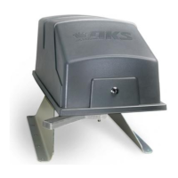
Pad Mount
Post Mount
Use this manual for circuit board 4502-010 Revision AA or higher.
EXTERNAL ENTRAPMENT PROTECTION MUST be
installed or the gate operator WILL NOT function.
6300-065-G-2-16
Questions and Answers:

DKS 6300 Series Specifications

General IconGeneral
ModelDKS 6300 Series
CategoryGate Opener
Horsepower1/2 HP
Warranty5 years
Control OptionsKeypad, Loop Detector, Push Button

Summary

QUICK GUIDE: DIP-Switches

SW 4 (Top 8 Switches)

Configures relay activation, exit loop output, auto-close timer, button input, dual operators, and tamper protect.

SW 3 (Bottom 8 Switches)

Sets gate opening direction, single/bi-parting gates, reverse/shadow loop, gate overlap, and monitored beams.

QUICK GUIDE: Main Terminal Descriptions

Terminal Functions and DIP-Switch Interaction

Details main terminal functions and their interaction with DIP-switch settings for gate operation.

SPECIFICATIONS

Gate Operator Specifications

Details models, horsepower, voltage, amp ratings, gate weight/length, cycles per hour, and speed.

Mounting Kit Dimensions

Provides dimensional diagrams for Pad Mount and Post Mount kits.

Important Safety Instructions

Installation Safety Guidelines

Outlines essential safety precautions and requirements for gate operator installation.

UL 325 Entrapment Protection

UL 325 Classifications Explained

Defines UL 325 gate operator classes (I-IV) based on gate type and location.

Entrapment Protection Types & Categories

Lists entrapment protection types (A, B1, B2, C, D) and corresponding gate operator categories.

Swing Gate Requirements

Entrapment Protection Areas

Specifies areas requiring entrapment protection based on gate opening distance and configuration.

Swing Gate Protection

Protective Devices and Features

Details protective measures like reverse loops, shadow loops, sensors, and warning signs.

SECTION 1 - INSTALLATION

1.1 Operator Position

Specifies the correct placement of the operator relative to the gate for 90° opening.

1.2 Post Mount or Pad Mount Base Assembly

Provides instructions and hardware details for assembling post and pad mount bases.

1.3 Underground Conduit Requirements

Outlines requirements for conduit installation, including wire type and bends.

1.4 Pad Mount

Details measurements and anchor requirements for securing the operator to a concrete pad.

1.5 Post Mount

Details measurements and considerations for mounting the operator on a post.

1.6 Arm and Gate Bracket Installation

Guides assembly of arms, elbow, and gate brackets, and initial adjustments.

1.7 Manually Adjust the Open and Closed Gate Positions

Explains how to manually set gate open/close limits using the operator's cycle.

1.8 Installation of Warning Signs

Instructs on mounting warning signs for hazard awareness.

1.9 Entrapment Protection Installation REQUIRED

Mandates installation of monitored photo sensors or reversing edges for operator function.

1.10 Gates Opening Wider Than 90°

Provides calculations and placement guidelines for gates opening beyond 90 degrees.

SECTION 2 - AC POWER TO OPERATOR(S)

2.1 High Voltage Wire Runs

Specifies wire size and distance limitations for AC power connections.

2.2 High Voltage Terminal Connections

Details wiring connections for 115 VAC power to the operator.

2.3 Bi-Parting Gates Wiring - Dual Gate Operators

Explains interconnection wiring for primary and secondary operators in a dual gate system.

SECTION 3 - ADJUSTMENTS

3.1 4502 Circuit Board Description and Adjustments

Identifies circuit board components and explains basic adjustments and LED functions.

3.2 DIP-Switch SW 3 & SW 4 Settings

Provides charts for setting DIP-switches SW3 and SW4 to configure operator functions.

3.3 DIP-Switch Definitions

Explains the function and effect of each individual DIP-switch on SW3 and SW4.

3.4 Automatic Open / Close Limit Adjustment

Details the process for automatically setting gate open and close limits using the operator's cycle.

3.5 Clutch Adjustment

Guides on adjusting the operator's clutch for proper slip sensitivity and entrapment protection.

3.6 Inherent Reverse Sensor System

Describes the automatic inherent reverse sensor system for entrapment protection.

SECTION 4 - WIRING

4.1 Main Terminal Description

Details the function of each terminal on the main control board for wiring connections.

4.2 Control Wiring

Illustrates wiring for access control devices like keypads, card readers, and control stations.

4.3 Auxiliary Terminal Wiring

Shows wiring connections for external entrapment devices and gate trackers to the auxiliary terminal.

4.4 Loop Detector Wiring

Explains how to wire loop detectors for vehicle detection and gate operation control.

SECTION 5 - OPERATING INSTRUCTIONS

5.1 Power and Reset Switches

Describes the location and function of the main power and reset switches.

5.2 Shutdown Conditions

Explains soft and hard (alarm) shutdown conditions and their causes.

5.3 Manual Gate Operation

Details how to manually operate the gate during power outages or equipment failures.

FAIL-SAFE Manual Operation

Describes the fail-safe method for manual gate operation during power loss.

SECTION 6 - MAINTENANCE AND TROUBLESHOOTING

6.1 Maintenance Schedule

Provides a monthly maintenance checklist for operator components and safety devices.

6.2 Troubleshooting Guide

Offers solutions for common operational problems, including power, motor, and gate movement issues.

6.3 Accessory Items

Lists available accessory items for the gate operator, including sensors, kits, and components.

Related product manuals