EasyManua.ls Logo

DKS 9050 User Manual

DKS 9050
42 pages
To Next Page IconTo Next Page
Page #1 background imageLoading...
Page #1 background image
Installation/Owner’s Manual
Model 9050
Model 9050
Model 9050
Copyright 2009 DoorKing, Inc. All rights reserved.
TM
Copyright 2011 DoorKing, Inc. All rights reserved.
Use this manual for circuit board 4702-010 Revision A or higher.
Date Installed:
Installer/Company Name:
Phone Number:
Leave Manual with Owner
Vehicular Slide Gate Operator
UL 325 Compliant
Circuit Board
Serial Number
and Revision Letter:
WARNING
MOVING GATE CAN CAUSE
Op
e
ra
te
ga
te on
ly
when g
a
t
e
area is in si
g
h
t
a
n
d
fre
e
of
p
e
o
p
le
a
n
d
o
b
s
truction
s
.
D
o
n
ot
a
llo
w child
ren
to play
in ga
te
a
r
e
a
or ope
rate
g
a
te.
Do
n
o
t
s
ta
n
d
in g
ate
p
a
th or walk
throu
g
h
path w
h
ile
gate is moving
.
Re
ad
owne
r’s
man
u
a
l
a
nd
s
afety
instructions.
SERIOUS INJURY OR
DEATH
CLASS
CERTI
FIED TO
CAN/CSA C22.2 NO. 24
7
C
ONF
ORM
S TO
ANSI/UL-325
VEHI
CULAR GATE OPERATOR
HP
5
3382
MODEL
SERIAL
VOLTS
PHASE
AMPS
60
Hz
MAX GAT
E LOAD
DoorKing, Inc., I
n
gl
e
w
ood, CA
9050-065-P-9-11
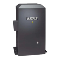
Table of Contents

Questions and Answers:

DKS 9050 Specifications

General IconGeneral
BrandDKS
Model9050
CategoryGate Opener
LanguageEnglish

Summary

Specifications

ASTM F2200 Standard for Gate Construction

Important Safety Instructions

Instructions regarding intended installation

Important Notices

UL 325 Entrapment Protection

Glossary

Slide Gate Requirements

Slide Gate Protection

SECTION 1 - INSTALLATION

1.1 Hardware for the Gate

Details gate hardware for smooth operation and safety.

1.2 Physical Stops for the Gate

Explains the necessity of physical stops for gate limit setting.

1.3 Typical Gate Types

Illustrates gate types compatible with the Model 9050 operator.

1.4 Operator Mounting Positions

Covers various mounting configurations like front, rear, and center.

1.5 Underground Conduit Requirements

Details conduit specifications for wiring installation.

1.6 Pad, Post or Ceiling Mount without / with J-Box Setup

Describes mounting options with or without junction boxes.

1.7 Mounting Operator and Chain

Guides on correctly mounting the operator and chain.

1.8 Installation of Warning Signs

Explains placement of warning signs for safety awareness.

SECTION 2 - AC POWER TO OPERATOR(S)

2.1 High Voltage Wire Runs

Provides guidelines for safe and effective high voltage wiring.

2.2 High Voltage Terminal Connection

Details connecting high voltage power to the operator.

SECTION 3 - ADJUSTMENTS

3.1 4702 Circuit Board Description and Adjustments

Explains the circuit board components and their settings.

3.2 DIP-Switch Settings

Details programming operator functions via DIP-switches.

3.3 Automatic Open / Close Limit Adjustment

Describes setting gate limits using automatic cycling.

3.4 Clutch Adjustment

Guides on adjusting the mechanical slip clutch for safety.

3.5 Inherent Reverse Sensor Adjustment

Explains how to adjust the primary entrapment sensor.

SECTION 4 - ENTRAPMENT AND SAFETY PROTECTION

4.1 UL 325 Terminal Description

Describes the 6-pin terminal for safety devices.

4.2 Secondary Entrapment Protection Device Locations

Illustrates placement of photo sensors and reversing edges.

4.3 Loop Detector Wiring

Details wiring loop detectors for vehicle detection.

SECTION 5 - MAIN TERMINAL WIRING

5.1 Main Terminal Description

Explains the function of each terminal on the main board.

5.2 Control Wiring for Single/Primary Operator

Shows wiring for single operator control devices.

5.3 Bi-Parting Gates Wiring - Dual Gate Operators

Details wiring for dual gate operator systems.

SECTION 6 - OPERATING INSTRUCTIONS

6.1 AC Power Switch and Reset Button

Explains operation of power and reset controls.

6.2 Shutdown Conditions

Describes soft and hard shutdown states and resets.

6.3 Manual Gate Operation

Details fail-safe and fail-secure manual release systems.

SECTION 7 - MAINTENANCE AND TROUBLESHOOTING

7.1 Maintenance

Outlines recommended maintenance intervals and checks.

7.2 Troubleshooting

Provides solutions for common operator malfunctions.

7.3 Accessory Items

Lists optional accessories available for the operator.

Related product manuals