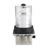
The FlexxPump 500 DLS is an extremely compact piston pump designed for lubricating oil. Its pistons operate with force-controlled and counter-rotating motion. The pump is available in versions with one, two, three, or four lubricant outlets, each secured by an integrated non-return valve. Approximately 0.15 cm³ of lubricant is dispensed with each pumping operation.
Function Description:
The FlexxPump 500 DLS requires connection to an external control unit, such as a PLC, for operation. It features an electrical interface that enables control and remote monitoring. Output signals from this interface provide information on the pump's condition and potential error messages, such as an empty grease cartridge. The FlexxPump 400 DLS-HE, a related model, is controlled by various input signals processed by microelectronics to deliver the ideal quantity of lubricant to lubrication points.
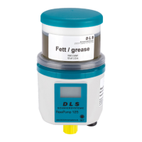
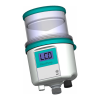
A key feature of the FlexxPump 500 DLS is its use of a special, non-exchangeable oil cartridge. This cartridge includes an integrated float that transmits a signal to the microelectronics when it is empty, ensuring timely awareness of lubricant depletion.
Important Technical Specifications:
- Product Designation: FlexxPump 500 DLS
- Part Numbers: 235-511-210; 235-512-210; 235-522-210; 235-523-210; 235-524-210
- Volume Cartridge: 400 ml
- Lubricant Type: Oil
- Dispensing Volume per Stroke: 0.15 cm³
- Electrical Interface: M12x1
Usage Features:
The FlexxPump 500 DLS is delivered in a cardboard box, which may include accessories like a lubricant cartridge or additional connection parts, depending on the ordered version.
Mounting and Installation:
- Removing the Housing: To access the power unit or fill the cartridge, the housing must be separated from the power unit by turning the retaining ring counterclockwise. Alternatively, the lid of the oil cartridge can be removed by turning it to the "OPEN" position and pulling it off. It is crucial to prevent dirt, water, or foreign bodies from entering the lubricant inlet during this process.
- Filling the Cartridge: The cartridge should be filled with oil up to the "max. Füllstand" mark. Care must be taken to ensure no contaminants enter the oil cartridge during filling.
- Assembling the Housing: After filling or maintenance, the housing is placed back onto the FlexxPump 500 DLS power unit and pressed down. The retaining ring is then turned clockwise until it snaps into place and is completely tightened. If only the lid was removed, it should be placed back onto the housing and moved to the "CLOSE" position.
- Connecting the Electrical Interface: Protective caps on the side of the FlexxPump 500 DLS must be removed, specifically the black cap from the M12x1 electrical interface. The pump is then connected to an external power supply or controller (PLC) using a suitable M12x1 connecting cable. Both straight and angled socket connection cables can be used, depending on the application. Refer to chapter 8.1 for connection cable conditions.
Commissioning:
- Mechanical Fastening: Securely fix the FlexxPump 500 DLS, paying attention to the maximum permissible tightening torques for the M5 female threads.
- Electrical Connection: Connect the pump to the external power supply or PLC via the M12x1 interface. This action switches on the FlexxPump 500 DLS.
- Assembly Check: Verify that the FlexxPump 500 DLS is properly and completely assembled, with particular attention to the voltage supply.
- Execute 12-Second Signal: Initiate the 12-second signal (refer to chapter 8.2.4 for details). The pump will execute a specific number of strokes, delivering lubricant from the cartridge to the outlet.
- Hydraulic Connection: Connect the consumer hydraulically to the FlexxPump 500 DLS. Ensure that tubes and connectors are installed tightly, cleanly, and correctly. Ideally, use tubes pre-filled with the appropriate lubricant.
- Check Settings: Verify the factory settings of the FlexxPump 500 DLS against the required values for the lubrication point and adjust them in the PLC program if necessary.
Operation and Settings:
The FlexxPump 500 DLS must be integrated into and controlled by a PLC. It delivers one or more strokes (0.15 cm³ each) based on external control signals. Output signals from the pump indicate its internal status (e.g., empty cartridge). Users should ensure their PLC program is correct for the application and that the lubrication point receives the proper amount of lubricant per time unit. If a special version of the FlexxPump 500 DLS is ordered, information on the supplement sheet takes precedence.
Maintenance Features:
A maintenance schedule must be followed for the FlexxPump 500 DLS:
| Maintenance |
Commissioning |
After 500 hours or after 3 months |
Every year |
If required |
| Cleaning |
X |
X |
X |
X* |
| Visual check |
X |
X |
X |
X* |
| Cartridge change |
|
|
X** |
X* |
* Depending on operating conditions and lubricant consumption
** Depending on delivery status (ordered version)
Oil Refill Procedure:
- Remove Housing: Separate the housing from the power unit by turning the retaining ring counterclockwise. Ensure no dirt or foreign bodies enter the lubricant inlet. Alternatively, remove the lid on top of the housing by turning it to "OPEN" and pulling it off.
- Fill Cartridge: Fill the cartridge with oil up to the "max. Füllstand" mark. Maintain cleanliness to prevent contaminants from entering the lubricant inlet.
- Assemble Housing: Place the dismantled housing onto the FlexxPump 500 power unit and press it on. Fasten the housing by turning the retaining ring clockwise until it snaps into place and is completely tightened. If the lid was removed for filling, place it back onto the housing and set it to the "CLOSE" position.
Defective or faulty electrical connections or unauthorized live components can cause serious injuries or death. All electrical connection work must be performed by qualified personnel. Damaged cables or plugs should be replaced immediately. Before any electrical installation work, the five safety rules of electrical engineering must be observed: unlocking, securing against unintentional restarting, checking for no voltage, grounding and short-circuiting, and covering adjacent live parts.