Do you have a question about the DLS FlexxPump 125 and is the answer not in the manual?
Defines signal words like DANGER, WARNING, CAUTION, NOTICE, INFORMATION used in the manual.
Explains the meaning of warning symbols such as general warning, electricity hazard, and flammable material.
Describes the system used to structure safety instructions within the manual.
Details the symbols used in text and instructions for requests, consequences, and additional information.
Specifies compliance requirements within the scope of the EC/EU Directive for machine installation.
Highlights dangers to the user or machine, emphasizing intended use and safe condition.
Defines requirements for qualified personnel authorized to operate the FlexxPump 125.
Identifies uses exceeding technical data as improper and prohibited.
Lists conditions for intended industrial use, including adherence to technical data and safety rules.
Outlines conditions that void warranty and liability claims for personal injury or property damage.
Provides critical safety instructions regarding electrical connections, lubricants, and handling.
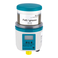
Overview of the FlexxPump 125's design, operation, and electrical interface.
Details the location of the CE mark and serial number on the pump's nameplate.
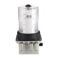
Explains variations in FlexxPump 125 versions and included accessories.
Presents detailed specifications for housing, hydraulics, and electrics of the FlexxPump 125.
Describes how the FlexxPump 125 is delivered, including protective measures and disposal of packaging.
Provides instructions and warnings for safely transporting the FlexxPump 125, avoiding shocks.
Details requirements for storing the FlexxPump 125, emphasizing protection from shocks and proper lifting.
Instructions for preparing the installation site and understanding safety guidelines before mounting.
Step-by-step guide for assembling the FlexxPump 125, including removing protective caps.
Details the steps for first-time commissioning, including mechanical, electrical, and hydraulic connections.
Key information about FlexxPump 125 operation, including modes, dispensing cycles, and cartridge types.
Describes default factory settings for Hour-Mode, Empty-Time-Mode, and Pulse-Control-Mode.
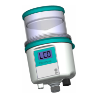
Explains how to navigate menus, interpret LCD displays, and use LEDs for status indication.
Lists and explains error codes (E1-E4) displayed on the LCD and their remedies.
Details the pin configuration for the M12x1 connector used in time-based control.
Maps LCD displays (OFF, ON, E1-E4) to output signals at PIN 4.
Illustrates high level (+24V) and low level (0V) output signals at PIN 4 and their meanings.
Defines the pinout for connecting the FlexxPump 125 to an external PLC via M12x1 interface.
Details control signal lengths (2, 12, 14 seconds) and their functions (1 stroke, FIL, error ack.).
Overview of output signals (OFF, PUL, errors) and specific error code messages (E1-E4).
Presents a schedule for cleaning, visual checks, and cartridge changes based on usage.
Describes how to perform visual inspections and clean the FlexxPump 125 and its system.
Outlines steps for recommissioning the unit after maintenance, including a 'Quick Check'.
Step-by-step guide for replacing the lubricant cartridge, emphasizing cleanliness and correct type.
Provides instructions for safely disposing of the FlexxPump 125 and its components.
Recommendations for installing the FlexxPump 125 near the lubrication point and using tubes if necessary.
Specifies the use of approved lubricants in original cartridges and how to identify them.
Provides detailed dimension drawings and installation guidelines for mounting the FlexxPump 125.
Official declaration stating compliance with relevant EU directives for machinery and EMC.
Illustrates the program flow chart for controlling the FlexxPump 125 via PLC in Pulse-Control-Mode.
| Brand | DLS |
|---|---|
| Model | FlexxPump 125 |
| Category | Water Pump |
| Language | English |