revision: 0
FlexxPump 125 (24V)
User Manual
25
EN-
SCHMIERSYSTEME
DIRECT LUBRICATION SYSTEMS
D L S
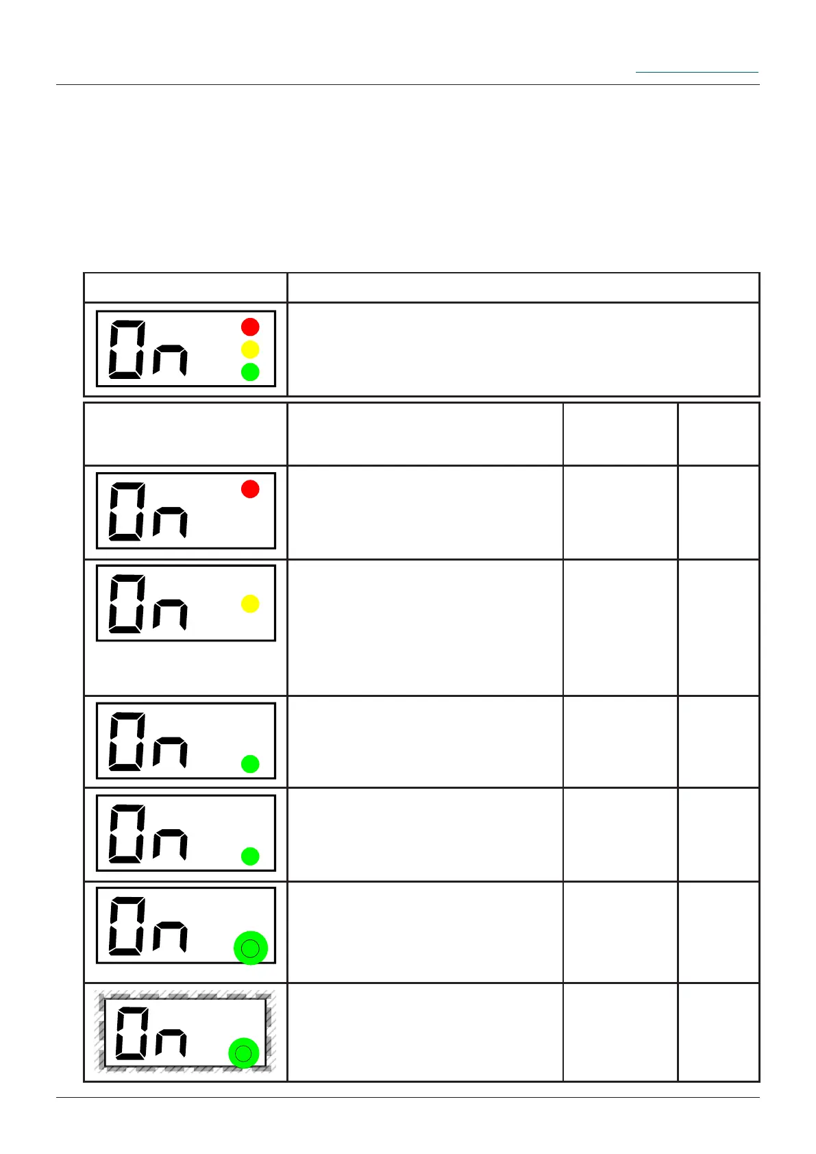
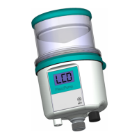
6.3.1 LCD
For optical output, information in the various states is displayed on the LCD via
FlexxPump 125. You will be supported by three coloured LEDs to the right of the LCD,
depending on the state of the FlexxPump 125. This allows you to assess the condition
of the FlexxPump 125 from a distance; the following applies: green: OK; red: Error. The
following tables show the LED assignment on the LCD as well as the explanation of the
respective output:
LCD Description Naming Detail
chapter
The red LED only lights up if
there is an error. The FlexxPump
125 must be ON before the error
occurs.
Error with
the Flexx-
Pump 125
6.4
The yellow LED only lights up if
the activation and programming
key has touched the action surfa-
ce (activation and programming
key detected).
Activation
and pro-
gramming
key detected
by Flexx-
Pump 125
6.3
The green LED lights up during
a dispensing process for approx.
10...18 seconds.
FlexxPump
125 dispen-
ses lubricant
6.3
The green LED lights up when
changes are possible and the
activation and programming key
was previously detected.
Changes
possible
6.3
The green LED ashes every 30
seconds when FlexxPump 125 is
ON and there is no error.
FlexxPump
125 is ready
for use
6.3
The green LED ashes 2x when
a value has been conrmed. In
addition to the green LED, the
LCD also ashes 2x.
Acceptance
of changed
value
6.3
Assignment (graphic) Assignment (in words)
upper LED: red
medially LED: yellow
lower LED: green