revision: 0
FlexxPump 125 (24V)
User Manual
51
EN-
SCHMIERSYSTEME
DIRECT LUBRICATION SYSTEMS
D L S
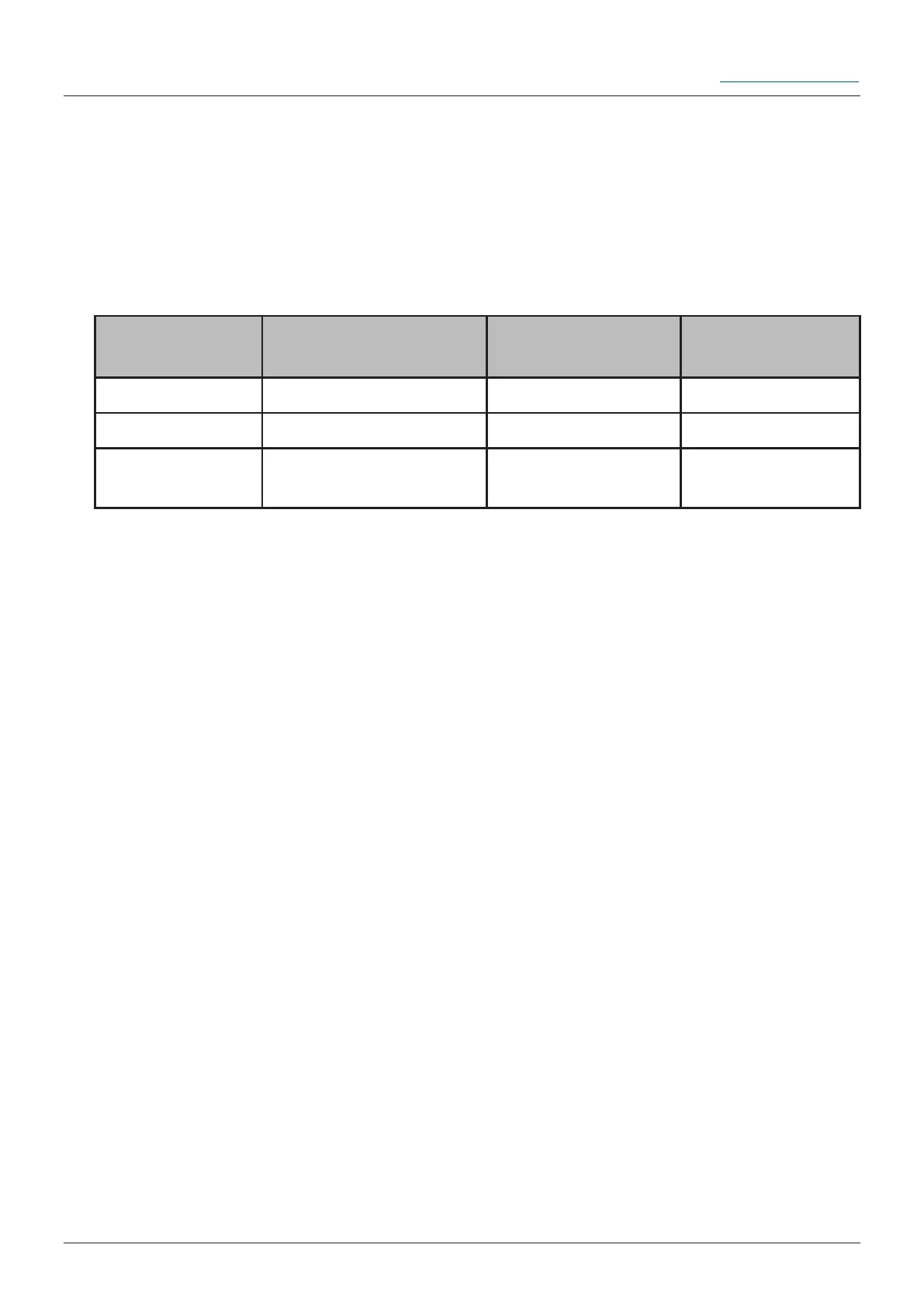
Signal length
in seconds
Description Function Detail
2 high
Signal 2 Seconds
1 Stroke Chap. 8.2.1
12 high
Signal 12 Seconds FIL-Function Chap. 8.2.2
14 high
Signal 14 Seconds Error acknowledge-
ment
Chap. 8.2.3
8.2 Input signals - External control (PLC)
The FlexxPump 125 provides the following unalterably dened control signals (input
signals), which must be transmitted from the PLC to the FlexxPump 125 via PIN 2 of
the electrical M12x1 interface as high level (+24 V DC).
The control signals must be generated as high level (+24 V) by the external controller
(PLC) over certain times with a tolerance of +/- 0.1 seconds.
The FlexxPump 125 in Pulse-Control-Mode PUL only processes the control signals
listed in the table up to a maximum length of 14 seconds. If a high level (+24 V DC) is
present outside the tolerances, the FlexxPump 125 does not react. If a high level (+24
V DC) is applied to PIN 2 of the electrical interface for longer than 15 seconds, the LCD
will display --- and the FlexxPump 125 will not react.