revision: 0
FlexxPump 125 (24V)
User Manual
75
EN-
SCHMIERSYSTEME
DIRECT LUBRICATION SYSTEMS
D L S
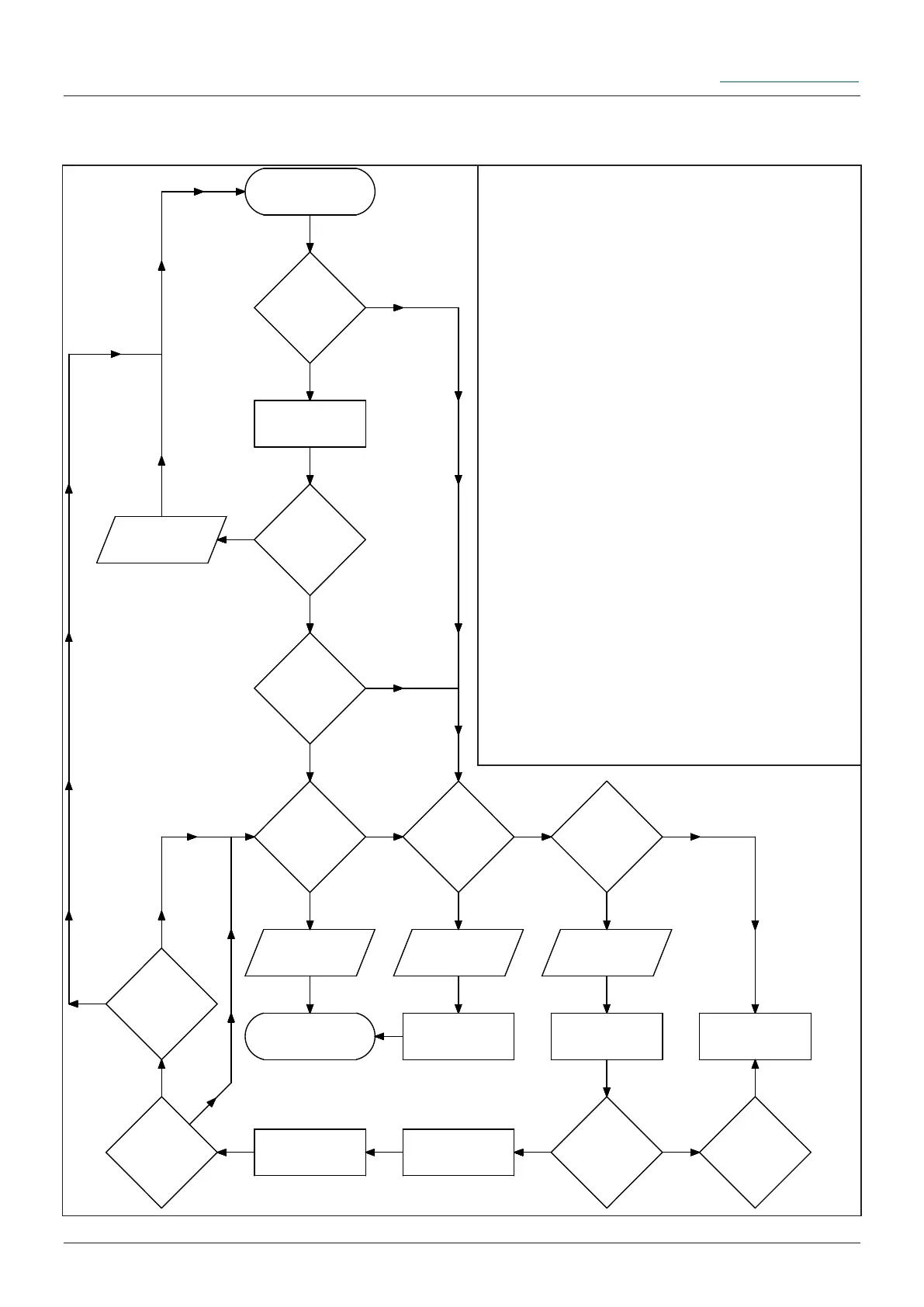
11.3 Flowchart Pulse-Control-Mode PUL
PIN 4
>3 Sekunden high?
nein
ja
Steuersignal 2 Sekunden
an PIN 2 senden
PIN 4
fallende Flanke?
ja
PIN 4
steigende Flanke
nach 7...17 Sekunden?
nein
ja
PIN 4
>3 Sekunden high?
nein
ja
Schmierung
erfolgrich!
PIN 4
0,5Hz Rechtecksignal?
nein
ja
Schmierung
erfolgrich!
Fehler E1; Kartusche leer
Kartusche wechseln
PIN 4
>3 Sekunden low?
ja
Schmierung
nicht erfolgrich!
Fehler E2 ... E4
LCD-Fehlermeldung
ablesen.
Fehler E2
oder E3?
nein
Fehler E4?
Abstellmaßnahmen
durchführen.
Steuersignal 10 Sekunden
an PIN 2
PIN 4
steigende Flanke
nach 10...11 Sekunden?
PIN 4
>3 Sekunden high?
FlexxPump demontieren
und an Hersteller
einschicken.
nein
Steuersignal
nicht erfolgrich
erkannt!
Start
ja
ja
ja
Start
neinja
nein
nein
The adjacent gure illustrates the basic
program ow chart for the control signal 2
seconds (chapter 8.2.1), which triggers a
stroke with 0.16cm³ lubricant on the Flexx-
Pump 125 in Pulse-Control-Mode, as well
as possible errors. This ow chart serves
as orientation when creating a separate
program for the external control (PLC).
Without this program it is not possible to
fully control and operate the FlexxPump
125 via an external control (PLC).
The information PIN 2 or PIN 4 refer
to the electrical M12x1 interface (chapter
8.1).
To create a program for using the FIL
function (chapter 8.2.2), proceed in the
same way, but instead of the control signal
for 2 seconds, use the control signal for 12
seconds.