revision: 0
FlexxPump 125 (24V)
User Manual
49
EN-
SCHMIERSYSTEME
DIRECT LUBRICATION SYSTEMS
D L S
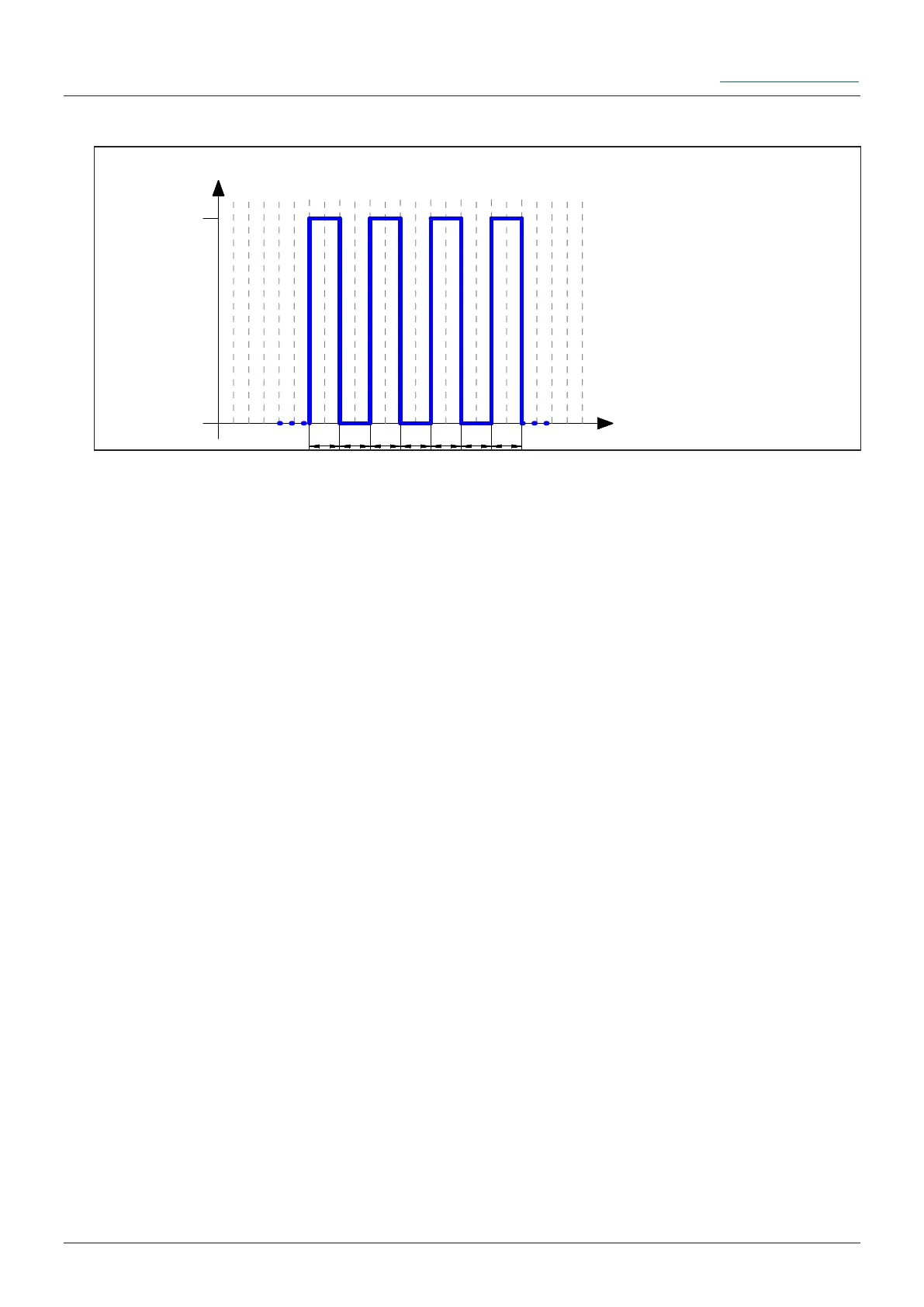
Output signal 0,5Hz-square wave signal at PIN 4:
24V
0V
t
PIN 4
1s 1s 1s 1s 1s 1s 1s
Description:
The integrated microelectronics of the FlexxPump 125 is equipped with an automatic
counter which counts the number of dispensing operations after a new and full car-
tridge has been tted. For a cartridge with 125ml lubricant there are 780 strokes, for a
cartridge with 250ml lubricant there are 1560 strokes. The small mathematical dieren-
ce is considered as protection against the entering of air into the hydraulic system. The
FlexxPump 125 does not pump lubricant! Find remedial actions in chapter 9.2.
8. Input and output signals - External control (PLC)
To command the FlexxPump 125 via an external controller (PLC), it is necessary to
switch the FlexxPump 125 to Pulse-Control-Mode PUL in the SET menu (chapter
6.3.7).
In Pulse-Control-Mode, the FlexxPump 125 operates as a pulse-controlled lubrication
system only if unalterable input signals (high level) are transmitted from the PLC to
the FlexxPump 125 via PIN 2 in a dened sequence. The FlexxPump 125 signals the
respective status to the PLC via high/low levels, which can be tapped o at PIN 4, and
thus enables comprehensive control or, by suitable programming of the PLC, dierenti-
ated evaluation of the dierent statuses. For the integration of the FlexxPump 125 into
an external control, one input and one output must be provided on the control side.