Do you have a question about the DMG Raffaello 2.8 and is the answer not in the manual?
Diagram illustrating the layout and connections for the DK3RFS00M.F0 basic version.
Diagram illustrating the layout and connections for the DK3RFS00M.FG full version.
Diagram illustrating the layout and connections for the DK3RF100M.F parallel input.
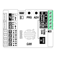
Diagram illustrating the layout and connections for the DK3RFC00M.F CAN BUS input.
Instructions for mounting using studs on 1.5-2mm thick faceplates.
Instructions for mounting using studs on a backplate for 1mm thick faceplates.
Details on connecting the device using the serial bus communication protocol.
Wiring diagram for cabin integration with the DMG Pitagora system.
Wiring diagram for cabin integration with different control units.
Wiring diagram for floor connections using the DMG Pitagora system.
Wiring diagram for floor connections with different control units.
Configuration options for the parallel wiring protocol, 1 wire per floor.
Setting up the display for car position indication (COP) or floor indication (LIP/LOP).
Configuration for common inputs in parallel wiring setups.
Configuration options for the parallel wiring protocol, 1 wire per segment.
Setting up the display for car position indication (COP) or floor indication (LIP/LOP).
Configuration for common inputs in parallel wiring setups.
Configuration options for the parallel wiring protocol using Gray or Binary code.
Setting up the display for car position indication (COP) or floor indication (LIP/LOP).
Configuration for common inputs in parallel wiring setups.
Protocol configuration for independent floor detection sensors.
Setting up the display to show the car's position with independent sensors.
Configuration for common inputs, specifically for negative logic with independent sensors.
Protocol configuration for parallel wiring with TKE, MEA, or Autinor systems.
Setting up the display for car or floor position indication with these protocols.
Configuration for common inputs when using TKE, MEA, or Autinor protocols.
Configuration options for the CAN BUS communication protocol.
Setting up the display for car position indication (COP) or floor indication (LIP/LOP) via CAN BUS.
Connecting service message inputs for cabin display position indication.
Connecting service message inputs for floor display position indication.
Advanced wiring instructions for external direction arrows.
How to adjust the volume levels for gong and buzzer alerts.
Configuring the display to function as a car position indicator (COP) or floor indicator (LIP/LOP).
Configuration options for direction arrows, including next direction input.
Enabling the "Car at Floor" indication using the "NEXT DIR." input signal.
Setting the offset values for different floor numbers displayed.
Configuring the initial display when the system starts or a floor is selected.
Configuring common settings for parallel position inputs.
Selecting various graphical elements for display customization.
Adjusting the display orientation (landscape, portrait, reversed).
Configuring the service message inputs for different communication protocols.
Procedure to reset all user-defined settings to factory defaults.
General options for customizing floor displays.
| Screen Size | 2.8 inches |
|---|---|
| Aspect Ratio | 4:3 |
| Response Time | 25ms |
| Resolution | 320 x 240 pixels |
| Display Type | LCD |
| Interface | Composite |
| Power Consumption | 3W |