Do you have a question about the DMP Electronics 734 and is the answer not in the manual?
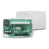
Receives and transmits data to the panel Keypad bus/AX-Bus.
Receives and transmits data out to other keypad(s) or module(s).
Used for devices drawing more than 10 Amps or exceeding relay limits.
Suppresses surges caused by energizing magnetic locks or door strikes.
Connects zones 1-3 and zone 4 for various device inputs.
Wiring for Wiegand readers: Data Zero, Data One, 12/24 VDC, and ground.
Wiring for OSDP readers: A (485), B (485+), DC+, and DC- connections.
Configure module address using DIP switches on the PCB.
Connects 12 or 24 VDC power supply to the module.
Instructions for programming the access control system.
The 734 Access Control Module is a device designed to integrate access control functionalities into a security system, allowing for the management of doors, card readers, and various zones. It serves as an interface between the main control panel and the access control components, facilitating communication and control.
The module's primary function is to provide access control capabilities, including the control of door locks (magnetic locks or door strikes), the integration of card readers (Wiegand and OSDP), and the monitoring of security zones. It receives data from the main panel via a Keypad bus or AX-Bus and transmits data to other keypads or modules. The module features a Form C relay for controlling door locking mechanisms, status indicator outputs, and multiple zone inputs for monitoring. It also includes a keypad programming header for configuration and a piezo for audible indications.
| Brand | DMP Electronics |
|---|---|
| Model | 734 |
| Category | Control Unit |
| Language | English |