INSTALLATION GUIDE
Model 400 USB Flash Module
Description
The Model 400 USB Flash Module allows you to easily eld update
rmware for panels that would otherwise require the use of a computer
and a Model 399 Programming Harness.
The Model 400 is equipped with a standard USB 2.0 compatible Type
A female connector for interface to a USB Drive, a 4-pin connector
between the Model 400 and the compatible panel, and an LED to
indicate panel update status.
Note: The Model 400 USB Flash Module is limited to RU les smaller
than 480k.
Compatibility
Compatible with XT30/XT50 Series panels, XTLC, XTLplus, and the
CellCom-LTE-V.
Caution: Do not connect a Model 400 to the CellComF-LTE-V if using 24 volt power.
Downloading the RU le to the USB Drive
To download a new rmware version RU le to the ash drive:
1. Connect a USB ash drive to your computer with a USB 2.0 compatible Type A female port.
2. Locate and download the panel’s rmware update RU le from DMP.com/Dealer_Direct and save it to the Root
directory of the ash drive.
3. When complete, disconnect the ash drive from your computer.
Note: The Model 400 only supports ash drives using a FAT32 le system. If multiple RU les are saved to the ash
drive, the le with the most recent Date Modied will be used by the Model 400.
Updating the Firmware
The Model 400 connects to the compatible panel via the panel’s programming PROG header. Updating rmware does
not change current panel programming. To update the panel with a new rmware version:
XT30/XT50
1. Remove the yellow and green wires from keypad bus terminals 8
and 9.
2. Connect the USB ash drive containing the RU le to the Model
400 and connect the assembly to the panel’s Programming PROG
header. The LED on the Model 400 will ash and then display
steady green.
3. Place a jumper across the Reset header.
4. Place a jumper across the Load header.
5. Remove the jumper from the Reset header.
6. Press and release the load button on the Model 400 to initiate the
rmware update. The LED on the Model 400 will ash slowly. If
the LED displays fast ashes it means the rmware update was
unsuccessful. The update will take approximately 4.5 minutes
and when complete the LED on the Model 400 will display steady
green.
7. Replace the jumper across the Reset header then remove the USB ash drive and Model 400 assembly.
8. Remove the jumper from the Load header.
9. Remove the jumper from the Reset header.
10. Reconnect the yellow and green wires to terminals 8 and 9.
In the event the Model 400 USB Flash Module is inadvertently removed from the panel before
the update nishes, repeat steps 1 through 10.
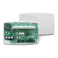
Bottom
Top
4-Pin Connector
USB Connector
Load Button
View LED
Figure 1: Model 400 USB Flash Module
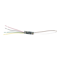
Figure 2: Model 400 USB Flash Module and
Flash Drive to XT30/50
J3
Phone
Line
J1
Ethernet
J16
Reset
J7 RJ
Supervision
J24
Celllular
header
connection
J18
Load
RED
PROG
J8
USB Flash Drive
4-Pin Connector
Model 400 USB Flash Module
Load Button on Underside
LED