800-641-4282
INTRUSION • FIRE • ACCESS • NETWORKS
www.dmp.com 2500 North Partnership Boulevard
Designed, Engineered and
Assembled in U.S.A.
Springeld, Missouri 65803-8877
LT-1402 © 2019 Digital Monitoring Products, Inc.
19151
Specications
Dimensions 3-3/8” L x 7/8” W x 1/2” H
Certications
FCC Part 15
CellCom-LTE-V, XTLplus, XTLC
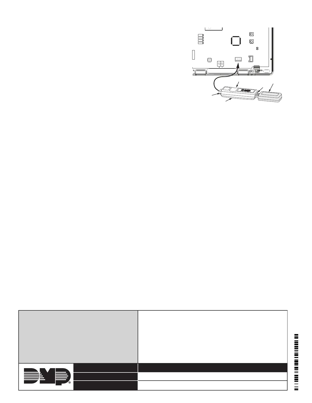
1. Connect the USB ash drive containing the RU le to the Model
400 and connect the assembly to the panels Programming PROG
header. The LED on the Model 400 will ash then display steady
green.
2. Press and hold the Load switch on the panel. While holding the
Load switch, press and release the Reset switch, then release the
Load switch.
3. Press and release the load button on the Model 400 to initiate the
rmware update. The LED on the Model 400 will ash slowly. If
the LED displays fast ashes it means the rmware update was
unsuccessful. The update will take approximately 4.5 minutes
and when complete the LED on the Model 400 will display steady
green.
4. Press and release the Reset switch then remove the USB ash
drive and Model 400 assembly.
In the event the Model 400 USB Flash Module is inadvertently removed
from the panel before the update nishes, repeat steps 1 through 4.
Verify the Firmware
1. At a keypad, enter the Diagnostic code 2313 (DIAG), and press CMD.
2. Press CMD until Panel Settings displays. Press any select key.
3. Press CMD until Firmware Version displays. Verify the panel rmware version is correct.
4. Press CMD until Stop displays. Press any select key to exit the Diagnostic menu.
Figure 3: Model 400 USB Flash Module and
Flash Drive to XTLC
USB Flash Drive
4-Pin Connector
Model 400 USB Flash Module
Load Button on Underside
LED
RESET
S1
LOAD
S2
BAT
J7
PROG
RED
PWR
SN
J1