716 OUTPUT EXPANSION MODULE
Installation Guide
DESCRIPTION
MODEL
716
TXD
NS
2
NC
NO
C
3
NC
NO
C
4
NC
NO
C
1
NC
1
12 VDC
12 VDC
12 VDC
12 VDC
2
3
4
NO
C
0
1
2
3
4
5
6
7
8
9
0
1
2
3
4
5
6
7
8
9
T
E
N
S
O
N
E
S
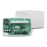
The 716Output Expansion Module
provides four independently
programmable Form C (SPDT)
relays and four zone‑following
annunciator outputs for use on
XR150/XR550Series panels.
Connect the 716Module to the
panel LX‑Bus. The 716Module
cannot be connected to the Keypad
Bus.
In addition to the panel onboard
Form C relays, you can connect
multiple modules to the panel
for unique auxiliary relays
and annunciator outputs,
one per zone. The XR550has
500available LX‑Bus zones. The
XR150has100available LX‑Bus
zones.
Compatibility
• XR150/XR550Panels
What is Included?
• One 716Output Expansion
Module
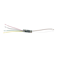
• One 20‑Wire Harness
• Hardware Pack
1
MOUNT THE MODULE
The716comes in a high‑impact plastic housing that you can
mount directly to a wall, backboard, or other flat surface. For easy
installation, the housing base contains holes that allow you to
mount themodule on a single‑gang switch box or ring. Mount the
module outside the panel enclosure.
1. Remove the housing fastener screws and separate the top
housing from the base.
2. Insert screws through the desired mounting holes on the
housing base. Refer to Figure 2for mounting hole locations.
3. Tighten the screws into place.
4. Attach the housing top to the mounted base with the
housing fastener screws. Refer to Figure 3.
Figure 1: 716 Module
Mounting
holes
Housing Base
Housing
fastener
hole
Housing
fastener
hole
Figure 2: Mounting Hole Locations
Figure 3: Assembling the Housing