2 716 INSTALLATION GUIDE | DIGITAL MONITORING PRODUCTS
3
Set the 716Module to an address that is used by the panel to turn outputs on and o. For easy addressing,
the716contains two on‑board rotary switches that you can set with a small screwdriver.
When using annunciator outputs, set the 716address to match the zones that you want the outputs to follow.
If you are only using the Form C relays, set the address to match the output numbers that you want to operate.
The module uses two rotary switches (TENS and ONES) to set the module address. Set the switches to match
the last two digits of the addresses. For example, for address 02set the switches to TENS 0and ONES 2 as
shown in Figure 4. For more information, refer to Table 1.
Note: Any 711, 714, 714‑8, 714‑16, 714‑8INT, 714‑16INT, 715, or other LX‑Bus device can be set to the same
address as a 716that is operating in unsupervised mode. Sharing an LX‑Bus address in this manner does
not cause a conflict between these devices. For more information, refer to “Unsupervised Operation”.
SWITCH
TENS ONES
XR150SERIES XR550SERIES
LX500 LX500 LX600 LX700 LX800 LX900
0 0 500 500 600 700 800 900
0 1 501 501 601 701 801 901
0 2 502 502 602 702 802 902
0 3 503 503 603 703 803 903
0 4 504 504 604 704 804 904
... ... ... ... ... ... ... ...
9 5 595 595 695 795 895 995
9 6 596 596 696 796 896 996
9 7 597 597 697 797 897 997
9 8 598 598 698 798 898 998
9 9 599 599 699 799 899 999
Table 1: LX‑Bus and Corresponding Zone Numbers
SET THE MODULE ADDRESS
WIRE THE MODULE
2
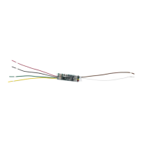
Refer to Figure 4when wiring the module. Connect the included20‑wire harness to the main header. Connect
red, green, and black wires to the panel LX‑Bus. For supervised operation, connect the yellow wire to the panel
LX‑Bus. Connect remaining wires as needed. For more information, refer to “Unsupervised Operation” and
“Supervised Operation”.
MODEL
716
TXD
1
NC
R
Y
G
B
NO
3
NC
NO
4
NC
NO
White/Brown
White/Red
White/Orange
White/Yellow
Switched Grounds (1 to 4)
Positive Voltage
50 VDC @ 50 mA max
To LX-Bus
RED
YELLOW
GREEN
BLACK
To Relay 1
To Relay 2
To Relay 3
To Relay 4
C
C
2
NC
NO
C
C
Relay Contacts
1 Amp @ 30 VDC
Data LED
Address
Switches
NC
NO
C
NC
NO
C
NC
NO
C
NC
NO
C
NS
1
2
3
4
0
1
2
3
4
5
6
7
8
9
0
1
2
3
4
5
6
7
8
9
T
E
N
S
O
N
E
S
7 mA + 28 mA
per active relay
Optional LED
Figure 4: Module Wiring
 Loading...