716 INSTALLATION GUIDE | DIGITAL MONITORING PRODUCTS 3
PROGRAM THE PANEL
Assign the Form C relays to outputs in Output Options and Zone Information, or assign the relays to Zone
Alarm Actions. For example, program the panel Telephone Trouble Output to operate output 520so that a
trouble on the panel phone line would toggle relay 1on a module set to address 520. Output 521would toggle
relay 2on the same 716module. The module’s four Form C relays are rated for 1Amp at 30VDC resistive. For
more information about programming, refer to the appropriate panel programming guide.
4
ADDITIONAL INFORMATION
Wiring Specifications
DMP recommends using 18 or 22 AWG for all LX‑Bus and Keypad Bus connections. The maximum wire distance between
any module and the DMP Keypad Bus or LX‑Bus circuit is 10 feet. To increase the wiring distance, install an auxiliary
power supply, such as a DMP Model 505‑12. Maximum voltage drop between a panel or auxiliary power supply and any
device is 2.0 VDC. If the voltage at any device is less than the required level, add an auxiliary power supply at the end of
the circuit.
To maintain auxiliary power integrity when using 22‑gauge wire on Keypad Bus circuits, do not exceed 500 feet. When
using 18‑gauge wire, do not exceed 1,000 feet. Maximum distance for any bus circuit is 2,500 feet regardless of wire
gauge. Each 2,500 foot bus circuit supports a maximum of 40 LX‑Bus devices.
For additional information refer to the LX‑Bus/Keypad Bus Wiring Application Note (LT‑2031) and the 710 Bus Splitter/
Repeater Module Installation Guide (LT‑0310).
Supervised Operation
To install the module as a supervised device, connect all four LX‑Bus wires from the module to the panel LX‑Bus and
program an appropriate zone as a Supervisory (SV) type. The module may use any address for supervision, provided
that a Supervisory zone is programmed for that address. For example, zone 504on an XR550Series panel would be
programmed as an SV zone to supervise a 716module set to address 04on the first LX‑Bus. Only the first zone number
for the programmed device is supervised. Refer to Table 1.
When installing Zone Expansion Modules on the same LX‑Bus as a supervised 716Module, address the Zone Expanders
to the next zone number. For example, on an XR550Series panel, the zone is 520for supervision and 521for a zone
expander on the same bus.
If a supervised 716Module loses communication with the panel, an open condition (Trouble) is indicated on its
Supervisory zone.
Unsupervised Operation
To operate the module in unsupervised mode, do not connect the yellow wire from the module to the panel LX‑Bus.
Unsupervised operation allows you to install multiple modules and set them to the same address. Do not program a
zone address for unsupervised operation. Unsupervised operation is incompatible with fire listed installations. For more
information, refer to “Compliance Listing Specifications”.
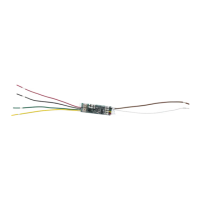
Annunciator Outputs (Switch‑to‑Ground)
Unlike the module Form C relays, the four power limited annunciator outputs on the 716Module follow the zone state
having the same address. For example, output 1 (white/brown) on a 716module set to address 120shorts to ground each
time zone 120is in alarm or trouble while armed. Use this feature to operate relays or LEDs to show changes in the state
of the panel armed zones. Refer to Table 2.
ARMED ZONE STATE 716ANNUNCIATOR OUTPUT ACTION
Normal O—No ground reference
Trouble, wireless low battery, missing On—Steady short to ground
"A" or "L" in Report to Transmit Pulse (1.6seconds On, 1.6seconds O)
Zone Bypassed Slow pulse (1.6seconds On, 4.8seconds O)
Table 2: Annunciator Outputs
 Loading...