User Manual
6/7
2.Click the effect button of panel to playback the chase of Recorder.
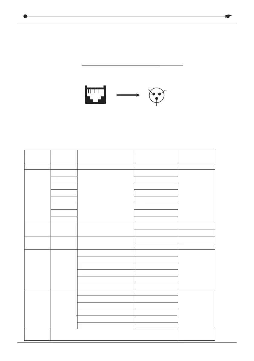
3.RJ45 network port line sequence:
Pi n 1:s i gn a l - P i n 2:si g n a l +
Pi n 3:G N D Pi n 4:5 V P i n5:5 V
Pi n 6:G N D Pi n 7:N C P i n8:N C
1- 8 1 - 8
XIII. RJ45 connector DMX signal head seat schematic
1-8
RJ45
1
2
3
T568B wire order:
1 2 3 4
Orange and white orange green white blue
5 6 7 8
blue white green brown white brown
Caron plug wiring line order:
1, brown white + brown
2, orange 3, orange and white
XIV.RS232 test form instruction
Baud rate:9600
Number
1
2
Mark
9A
Hexadecimal
code
Instruction
Remark
Central control
Our equipment
Central
control
address
00
01
02
03
04
05
06
07
Setting of
Menu
1. Unit ID
1
2
3
4
5
6
7
8
9A
3
4
5
00-01
Blackout button
00
01
Light off
Light on
00-01
Play button
00
00
00
01
+1
+2
+4
+8
Light off
Light on
00-0F
Chase 1
No selected Chase (Origin)
No selected Chase (Origin)
Chase 2
Chase 3
Chase 4
Chase 5
Chase 6
Chase 7
Chase 8
Chase 1~4
Chase 5~8
6
+1
+2
+4
+8
0F
0F
00-0F
7
Check
character
It is equal to the sum of bytes 1+2+3+4+5+6.
Then subtract 80.
DMX RECORDER SERIES