1-14 (No.HD003<Rev.004>)
2.6 Check details after mounting separately sold parts
Item Check details Required tools
1 Reform H unit The warpage of the printed card should be within the specs (1.5
mm).
Blank card
2 IC Contact unit Check the IC contact position mark using a blank card and a
contact label.
• Service mode > Offline Test > Test the IC (Contact).
• If the position is out of specs, Maintenance > OffsetContact to
adjust the position. (See 2.3.1 IC contact position adjustment)
Blank card, Contact label
The card written with an application should be read by the read-
er.
(Check in the USB and Ethernet connections)
Contact IC card
Contact IC reader
3 MG Unit Service mode > Offline Test > test the MG.
• The test should be finished normally.
MG card
The card written with an application should be read by the read-
er.
• There is no adjustment for an MG unit after mounting because
MG units are shipped after being position adjusted. Check for
normal operation only.
MG reader
4 Running after mounting the
separately sold parts
(For all separately sold parts)
Test for normal printing on about 10 cards
• Service mode > Offline Test > print
Evaluation card
Item Item Conditions & specs Test point
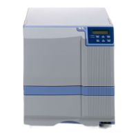
5 Safety test (for
all separately
sold parts)
Withstand
voltage test
Timer Leak current Test voltage (With the POWER SW: ON)
GND C on the AC inlet in the
drawing below
|
Bipolar B on the power cord in
the drawing below
2 to 3 sec. 30mA AC1600±50V
Insulation re-
sistance test
Test voltage Insulation resistance value
DC 500V 100M and over
Grounding
continuity test
Timer Test current Spec value (With the POWER SW: ON)
Screw A on the top left of the
rear panel in the drawing below
|
GND C on the AC inlet in the
drawing below
3 to 4 sec. AC25A 0.1 or under
(Without power cord)
A
B
C