F6000 Family of Power System Simulators User Guide
72A-1589 Rev. C 02/01 7-15
D
DD
D
R
RR
R
A
AA
A
F
FF
F
T
TT
T
3
33
3
/
//
/
5
55
5
/
//
/0
00
0
1
11
1
To remove the communications board from the instrument front panel:
1. Remove the two Phillips head screws that secure the communications
board to the front panel.
2. Tilt the front panel up until it leans against the instrument.
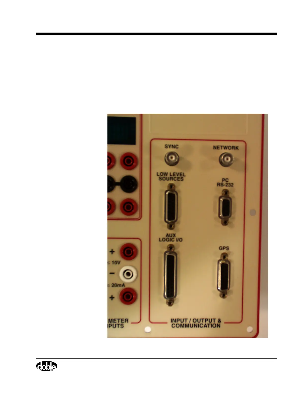
3. Use an open-ended wrench or pliers to remove the 8 nuts on the right
side of the front panel (two for each of the four connectors).
See Figure 7.10.
.
Figure 7.10 Right Side of the Instrument Front Panel
Use PIC00013a.tif on page 12.