Dark time
DOEPFER
Functions
10
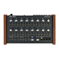
position other than the previously selected ones, these steps will become the new start and end points. If
you set steps to ”Jump” within the previously selected range, they will not affect the sequence in any way.
Confusing, eh? Not really, go ahead, and with a little practice you will see how useful this little feature is:
Using these pretty simple settings, you may create quite interesting and ever-changing complex musical
patterns. You may completely ”reprogram” the sequence by just the ick of a switch or two. Give it a try and
you will get an idea why analog sequencers enjoy great popularity, especially within live electronic music
contexts. Once you have got the hang of it, you will get great results and endless hours of sequencing
excitement.
Oops – here‘s a hidden function: Setting both step status switches of steps 1 and 9 on ”Jump” resp.
”Skip” will entirely disable their corresponding row.
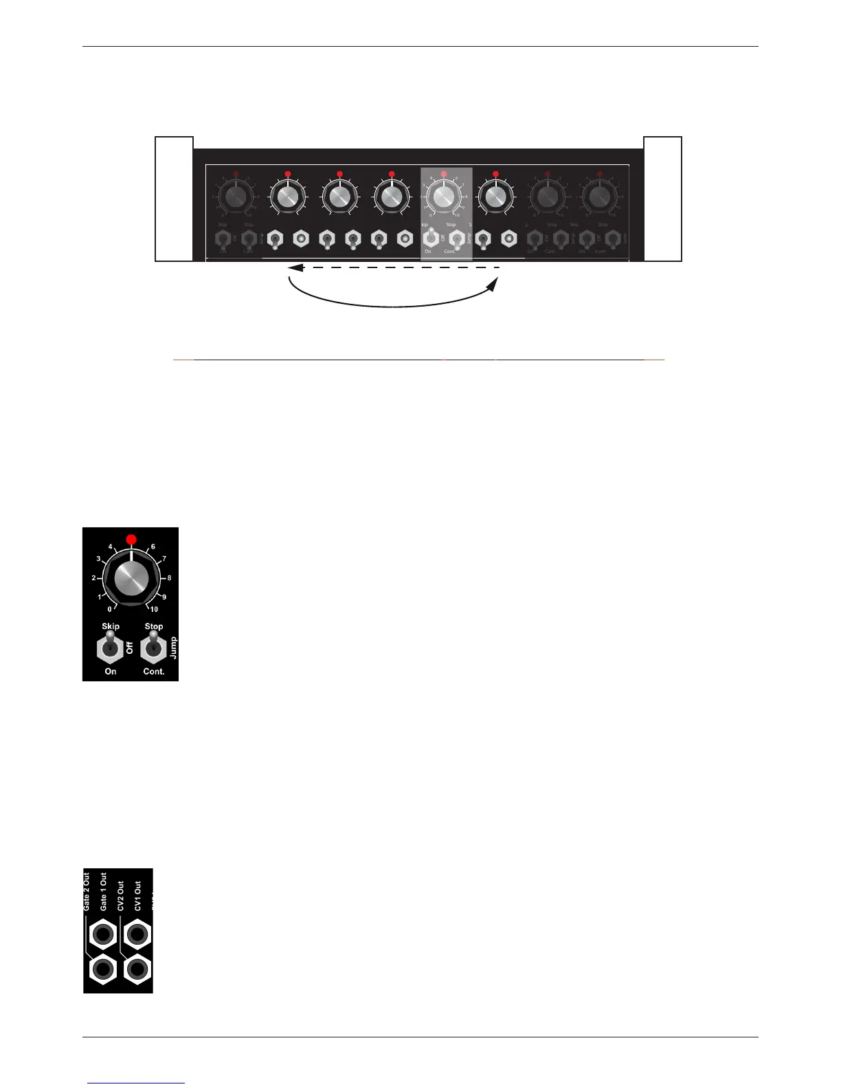
• LED
The status LED will light up when the corresponding step has been reached and
show the current position of the sequence.
• Step-knob
– This control determines the pitch of the respective step. The behavior of this pot
(and all other step controls) depends on the settings of the ”Range” and
”Quantize” switches. More about this in chapter 3.1.3., ”Sequence Control” on
page 11.
– In Custom mode, the lower eight step controls determine the individual gate time
for the corresponding upper eight steps. You will nd a description in
chapter 3.1.5., ”Individual Gate Time for Steps 1 – 8” on page 14.
3.1.2. CV/Gate output sockets
Each step set to ”on” will generate several signals at a time when active. These can be tapped from the
sockets on the rear interface panel of Dark Time. They can be used to control other sound sources
connected.
• Gate 1 / 2 Out
– Gate 1 Out delivers gate signals of steps 1 – 8 (+5V/+12V).
– Gate 2 Out delivers gate signals of steps 9 – 16 (+5V/+12V).
(An internal jumper-setting determines a gate signal voltage of +5V or +12V.
Please refer to page 21, section 3.4.)
• CV 1 Out / CV 2 Out
– CV 1 Out delivers control voltage of steps 1 – 8.
– CV 2 Out delivers control voltage of steps 9 – 16.