Functions
Dark time
DOEPFER
17
3.2.3. Analog Interface
Of course, Dark Time allows interaction with non-MIDIed equipment. It will perfectly t into an analog setup.
The necessary connections can be made via the rear analog interface panel of Dark Time. It sports twelve
1/8” sockets with in- and outputs.
CV/gate outputs:
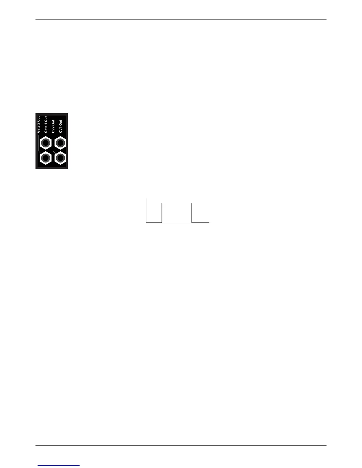
Let’s have a closer look at the connectors, shown in the gure below. Here, both step registers send out
control voltages and gate signals individually. These signals are necessary to control an external analog
synthesizer.
• The voltage levels sent out from the CV 1 Out and CV 2 Out sockets depend on the
setting of the step controls, the transpose and the range switches. The most common
use is controlling the pitch of an external synthesizer. The sockets provide a voltage
range between -2V and +10V. Of course these voltages cannot only be used for
controlling the pitch of a synthesizer, but also for controlling other parameters like
e.g. lter cut-off frequency, VCA amplitude, you name it.
• The sockets labeled Gate 1 Out and Gate 2 Out send out – you have already
guessed it – a gate signal, again for each register individually. Active sequencer
positions put out a signal of +5V/+12V at these sockets. The duration of a gate signal
depends on the setting of the Pulsewidth control (s. page 13).
Gate off on off
The gate signal triggers the envelope generator of an external analog synthesizer which, in turn, will gener-
ate an audible tone as one envelope generator is commonly used to control the amplitude of a VCA.
Some vintage synthesizers require a gate signal of +10V or higher (e.g. ARP 2600). In order to match also
withh these machines, Dark Time gate output level can be changed from +5V (default) to +12V by setting of
an internal jumper. Please refer to page 21, section 3.4.
Since Dark Time puts out control voltage and gate signal of both registers individually, some interesting
tricks can be achieved, e.g.:
• Control two synthesizers in parallel with two eight-step sequences.
• Control two different parameters of one synthesizer at the same time.
CV Inputs:
The inputs CV 1 In and CV 2 In take external control voltages within the range of 0V and +5V. These vol-
tages will be added to the voltages generated by the step registers. Both registers may be addressed
separately, with CV1 In corresponding to the upper register and CV2 In to the lower.