Dark time
DOEPFER
Functions
14
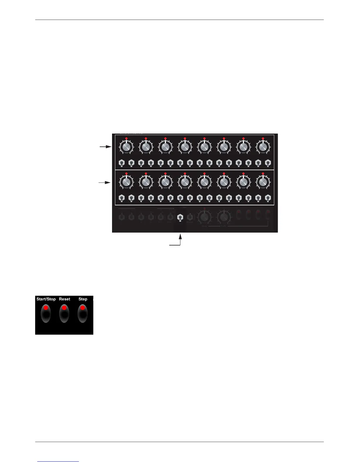
3.1.6. Transport keys
These three keys control the so-called transport functions of Dark Time.
• Start/Stop key
Hitting the Start/Stop key once will get the sequencer going. Hitting it once
again, the sequencer will stop. The next hit will restart the sequence and play
back will continue from where it was stopped. In other words: If the sequence
was stopped on step 8, the sequence will continue from step 9 when hitting
Start/Stop.
• Reset key
Hitting the Reset key will reset the sequence to the rst active step. This can
be step 1 (1-16 mode), step 1 and 9 (2x(1-8) mode) or any step in ”jump”
position which determines the current starting point of the sequence.
• Step key
The rst hit will activate the Step key function. Each new hit on this key will
make the register skip one step forward to the next step available. This way
you can step through the sequence manually. Hitting the Stop key will quit
this function.
ShueDivide
O
Jump
Jump
Jump
Jump
Jump
Jump
Jump
Jump
O
O
O
O
O
O
O
O
Jump
Jump
Jump
Jump
Jump
Jump
Jump
Jump
O
O
O
00
2V
Scale
Random
Random
1-16
O
O
O
O
Stop Stop Stop Stop Stop Stop Stop Stop
Stop Stop Stop Stop
+1
61-961-9
Stop Stop Stop Stop
Skip Skip Skip Skip Skip Skip Skip Skip
Skip Skip Skip Skip
1V OUp Up 2x(1-8) Internal
External
+1
8-18-1
Skip Skip Skip
Start/Stop Reset Step Function
Skip
On On On On On On On On
On On On On
5V On Down Down 1-8
Combi
Midi/USB-1
On On On On
Cont. Cont. Cont. Cont. Cont. Cont. Cont. Cont.
Cont. Cont. Cont. Cont.
-1
Cont. Cont. Cont.
PulsewidthClockTranspose Range Quantize Direction Link Sync
Cont.
0000000
00
0
0
0000000
4444444
44
4
44444444
6666666
6
5
6
6
66666666
1111111
11
1
11111111
3333333
33
3
3333333
3
2222222
22
28888888
88
8
88888888 22222222
01010101010101
1010
10
0101010101010101
9999999
9
9
9
99999999
7777777
77
7
77777777
Pitch
Step-lenght
”1-8 Combi“
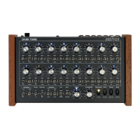
3.1.5. Individual gate length for steps 1 to 8:
As you already know, the Pulsewidth control sets the gate time. This setting affects all steps by the same
factor. Now you will learn how to program individual gate time settings for each of the steps 1 to 8 (upper
register).
This function is enabled by the ”Custom” setting of the Link switch.
• Set the Link switch to ”Custom” position.
• Simply turn the step controls of the lower register to program individual gate time settings for the
corresponding steps of the upper register, e.g. use step pot 9 to adjust the gate time of step 1 and
so on. In this mode, the setting of the gate time is continuously variable, i. e. it is not dependent on
the clock divider settings.