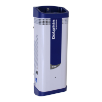
OPERATING MODES
MODE
Charging
Balancing
Floating
Internal
temperature
fault «Temp»
Abnormal
output voltage
fault «Volt out»
Battery fuse
fault «Bat fuse»
MODE
AC
On/Off
LED.1
Yellow
steady
Yellow
ashing
Green
ashing
Red
ashing
Red
steady
Rouge xe
LED.2
Yellow
steady
STATUS
Batteries are being charged.
Charging phase time varies up to 6
hours, depending on the battery’s
initial charge level.
End of battery charging phase.
Balancing phase time varies
between 30 minutes and 4 hours,
depending on the battery’s initial
charge status.
Batteries are charged.
Charger is in standby for a period
between 30 seconds and 10
minutes.
Restarting is automatic when the
fault is cleared.
4Check climatic conditions,
internal fan operating properly,
charger space volume.
Charger is in standby for a period
of 30 seconds.
Restarting is automatic when the
fault is cleared.
4The electronics board is probably
permanently defective.
Battery fuse is defective.
4Check connections, polarity
and battery charge status.
STATUS
Electricity cabinet power on
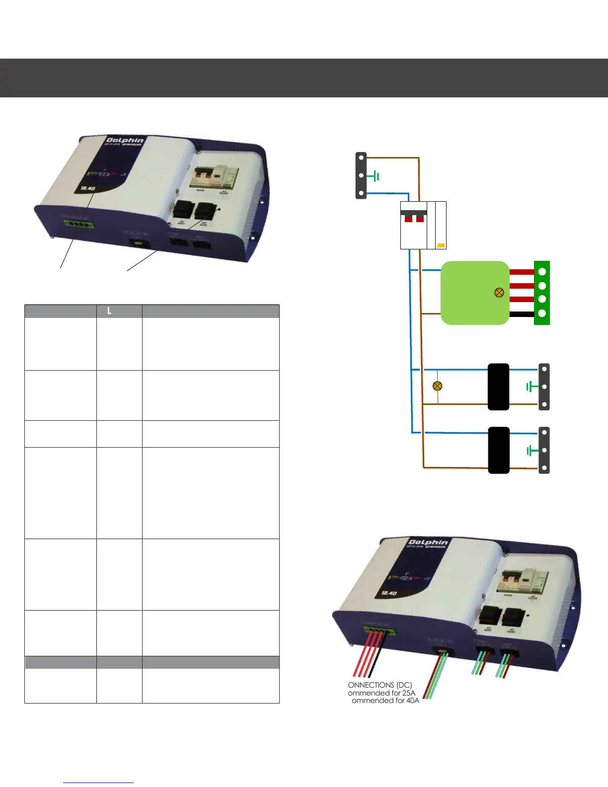
CONNECTIONS
BATTERY CONNECTIONS (DC)
6mm2 recommended for 25A
10mm2 recommended for 40A
EN
LED1 LED2
AC CONNECTIONS
3 x 2.5 mm2 recommended