4
EN
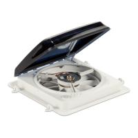
General Information Dometic Fan
3 General Information
I
The images used in this document are for reference
purposes only. Components and component
locations may vary according to specific product
models. Measurements may vary ±0.38 in. (10mm).
3.1 Tools and Materials
Dometic recommends that the following tools and
materials be used while installing the appliance.
Required Hardware (Installer Supplied)
Insulated Connectors
18 #8 x 1 in. PHPH T/S Zinc Screws
Minimum 16-gauge Stranded Copper Wire
• Black = Positive or Fused
• White = Negative or Ground
Optional Components and Kits
1
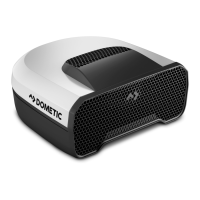
Ultra Breeze Vent Cover
Ultra Breeze Installation Kit
Trim Garnish
Pop N’ Lock Screen (2-pack)
Clamp Garnish Screw Pack
• 4 #10 x 2 in. PHFH T/S Zinc Screws
• 4 #10 x 4 in. PHFH T/S Zinc Screws
• 4 #10 x 3 in. PHFH T/S Zinc Screws
1
Available as an accessory (not included).
Recommended Tools
Crimping Tool Straight Edge
Marking Pen or Pencil Stripper Tool
Measuring Tape Utility Knife
Multimeter Wire Cutter
Phillips Screwdriver/Bit Waterproof Sealant or Lap
Sealant
2
Putty Knife or Scraper
2
Do not use silicone or oil-based sealants.
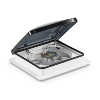
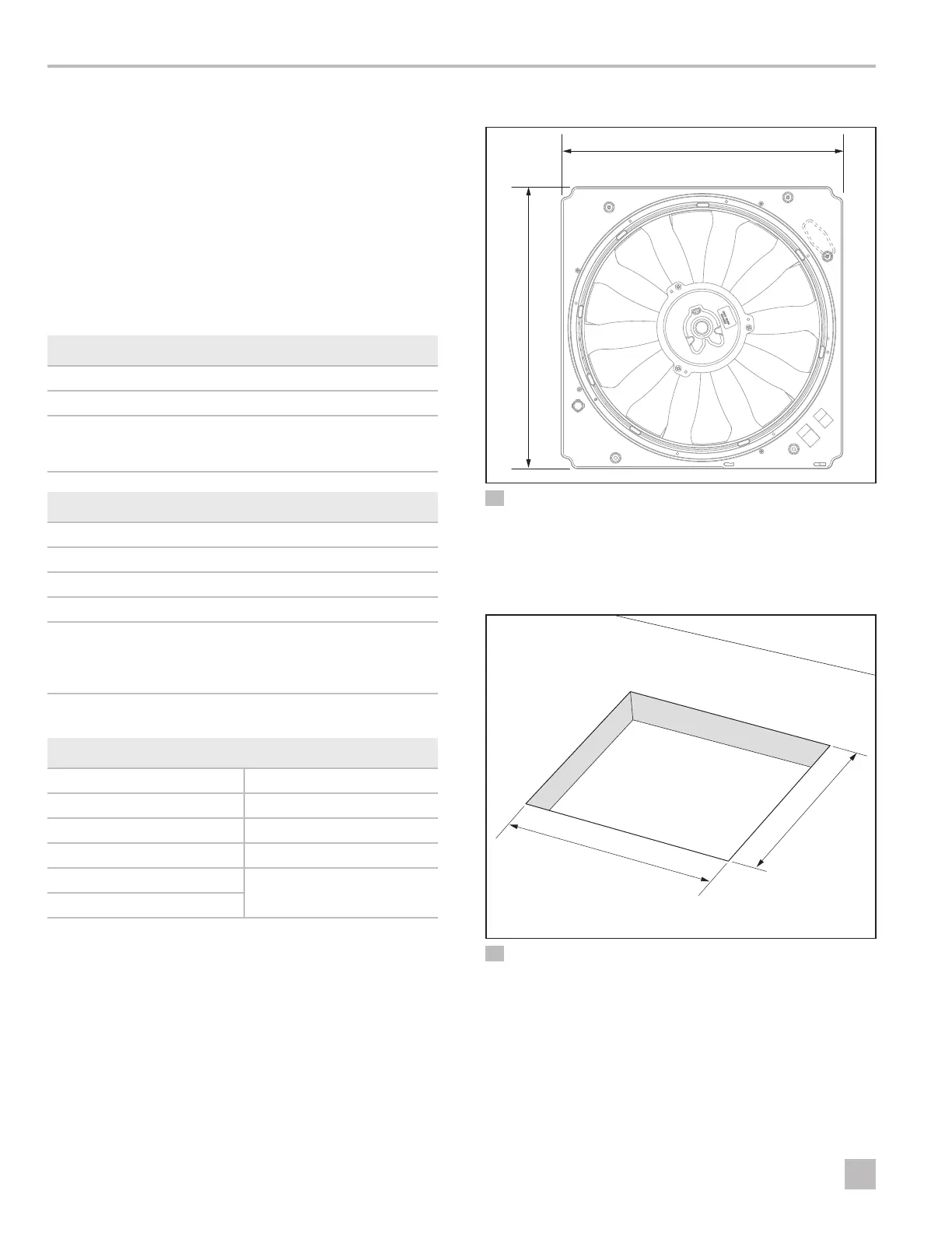
3.2 Fan Dimensions
qq
ww
1 Fan Dimensions
q
14.0 in. (356 mm)
w
14.0 in. (356 mm)
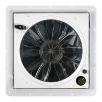
3.3 Fan Cut-out Dimensions
qq
ww
2 Fan Cut-out Dimensions
q
14.5 in. (368 mm)
w
14.5 in. (368 mm)