8
H. Placing The Unit On The Roof
1. Remove the unit from the carton and discard car-
ton.
2. Place the unit on the roof.
3. Lift and place the unit over the prepared opening
using the gasket on the unit as a guide. See FIG.
7.
4. Place the return air cover kit inside the RV. This
box contains mounting hardware for the unit and
will be used inside the RV.
This completes the outside work. Minor adjustments can
be done from inside the RV if required.
Personal injury hazard. This unit weighs approximately
100 pounds. To prevent back injury, use a mechanical
hoist to place unit on roof. Failure to obey this warning
could cause severe personal injury.
Property damage hazard. Do not slide the unit. Fail-
ure to obey this warning may damage the neoprene
gasket attached to the bottom and create a leaky in-
stallation.
FIG. 7
FRONT
Lift And Place
Do Not Slide
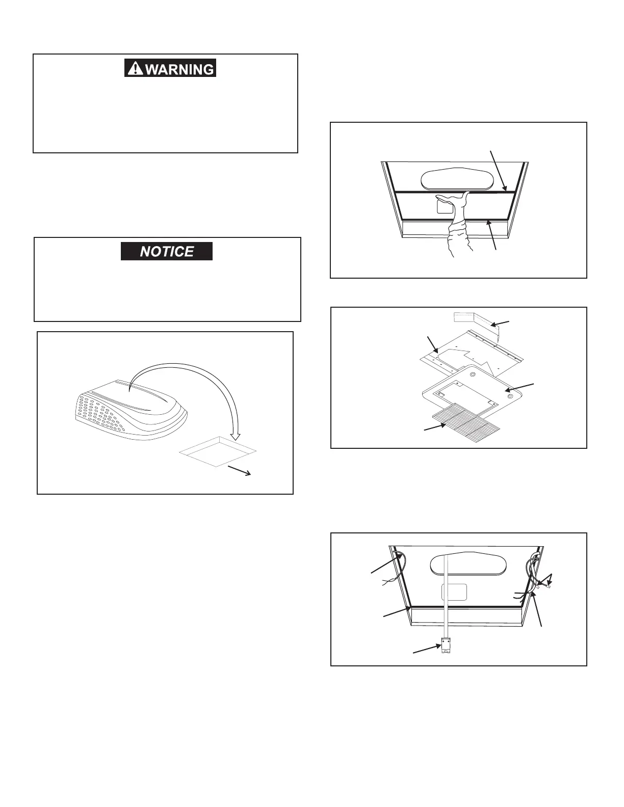
I. Installing The Unit
1. Check gasket alignment of the unit over the roof
opening and adjust if necessary. Unit may be
moved from below by slightly lifting. See FIG. 8.
When installing 3105007.XXX or 3105935.XXX
return air kit, remove gasket strip from bottom of
base pan and discard.
2. Remove return air cover and ceiling template from
carton.
3. All models listed in this manual will use a four (4) bolt
pattern for installing the return air cover kit. These
bolts are furnished in part number 3100895.006
(bolt kit) and is purchased separately.
4. Reach up into the return air opening and pull the
unit electrical cord down. See FIG. 10.
5. Hold the ceiling template up to the 14-1/4" x 14-1/4"
(±1/8") opening. Be sure the large plate faces the
rear of the RV.
6. Start each mounting bolt through the ceiling tem-
plate and up into the unit base pan by hand. Install
wood screw in each end of the ceiling template.
This insures a tight t of the return air cover to
ceiling. See FIG. 11.
Divider Plate
Ceiling Template
Return Air
Cover
Return Air
Grill
FIG. 9
FIG. 10
AC Power
Supply
Control
Cables
Furnace
Wires
Gasket
Electrical
Cord
FIG. 8
Center Unit From Below
Roof
Gasket
Remove Gasket Strip