10
PRE-INSTALLATION
Air Discharge Configuration Examples
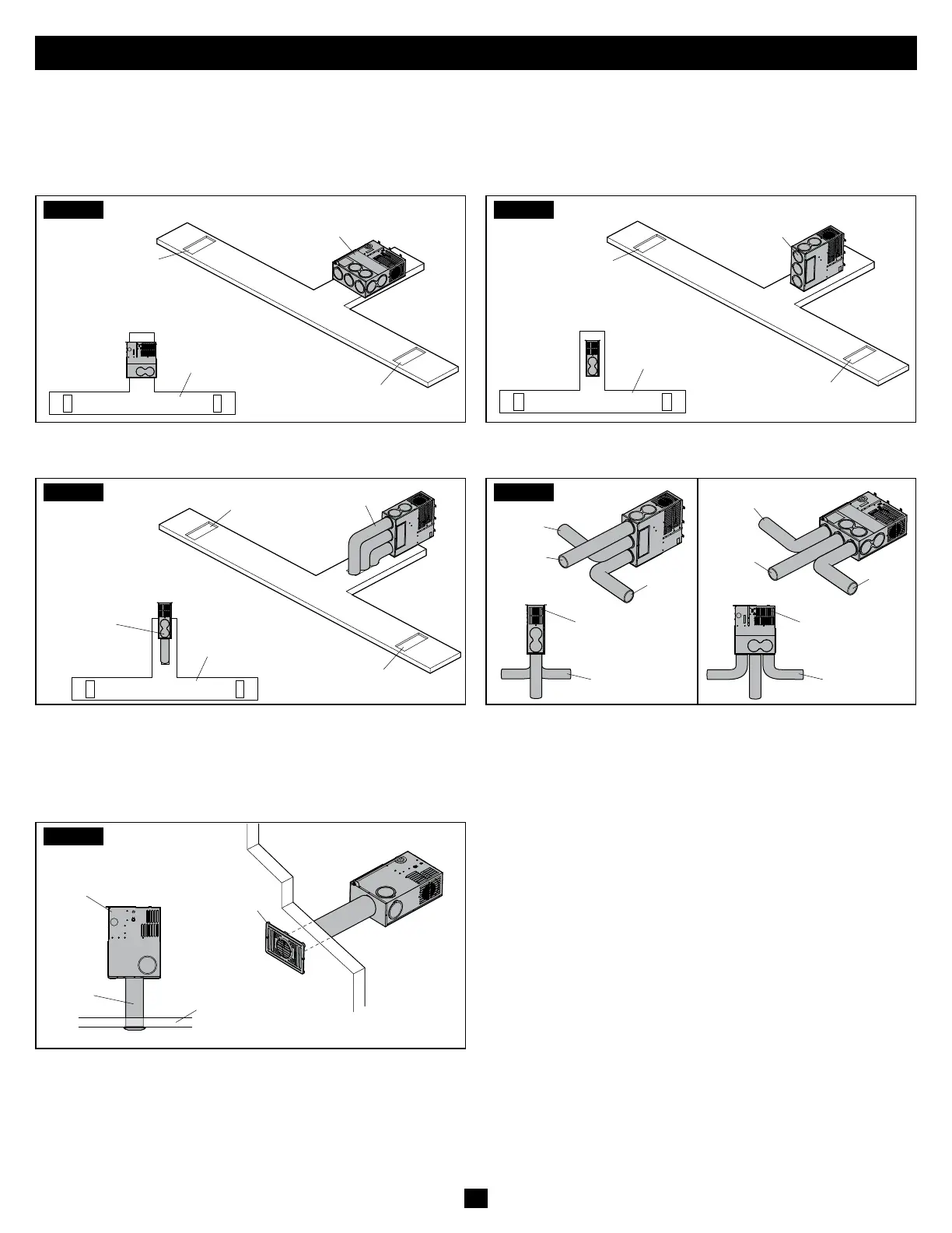
The following figures offer a visual representation of the detailed discharge requirements outlined in the “Air Discharge
Requirements” tables on page 11 and page 12. These examples show vertical and horizontal installations, using different
Furnace models and ducting options.
FIG.1
(Top View)
Hard Ducting
Register
Register
Medium or
Large Furnace
• Horizontal Furnace – Bottom exit into hard ducting
FIG.2
Hard Ducting
Register
Register
Medium or
Large Furnace
(Top View)
• Vertical Furnace – Bottom exit into hard ducting
FIG.3
Medium or Large
Furnace Only
4" Flex
Ducting
Hard Ducting
Register
Register
(Top View)
• 4" flex ducts into hard ducting
For medium and large Furnaces: ducts 8 and 9 are used for
additional ducting only, and are not used to calculate the
required discharge area shown at the bottom of page 11.
FIG.4
Small, Medium,
or Large Furnace
(Vertical Mount)
Small, Medium, or
Large Furnace
(Horizontal Mount)
4" Flex Ducting 4" Flex Ducting
Duct 4
Duct 5
Duct 4
Duct 3
Duct 5
Duct 3
(Top View) (Top View)
• Make sure to use at least the minimum number of 4" flex
ducts required for your model size. See “Air Discharge
Requirements” on page 11 and page 12.
FIG.5
Small
Furnace
Only
Interior Grill
Cabinet Cutout
Location
5" Flex
Ducting
(Top View)
• 5" ducting over 12" long must have an additional 4" duct
added to the system.
To aid in the removal of the Furnace through the grill
cutout for servicing, when using a front interior grill, orient
the grill to the direction of the Furnace: horizontal if the
Furnace is horizontal, vertical if the Furnace is vertical.
 Loading...