14
EN
Furnaces
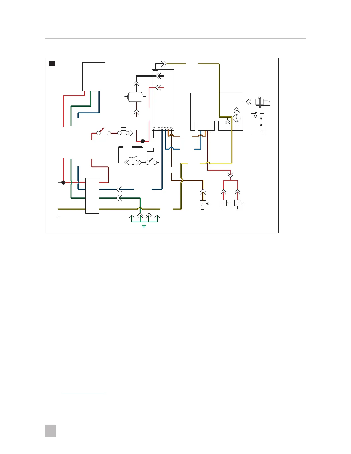
Two-Stage Models (1522, 2334, and 2540)
6 5 4 3 2 1
1 2 3 4 5
6
10
Electrode
Dual-
Control
Power
Switch
Limit
Switch
Sail
Switch
Circuit
Breaker
Motor
Ground
-12
VDC
+12
VDC
Low
Valve
Main
Valve
GV
Redundant
Valve
Thermostat
Case
Bulk
Head
Ignition
Control
5ON-12
Black
(Ground)
Orange
White
White
Black
Low
Valve
Ground
Ground
Ground
High
Voltage
Power to
High Valve
Power from
Thermostat
Power to Thermostat
Ground to Thermostat
Signal from Thermostat to Board
Power to
DSI Board
Power to
Motor
Power to On/
Off Switch
Power to
Board
I
The only compatible thermostat for the two-stage furnace is the Atwood digital thermostat (PN#38535).
Sequence of operation for two-stage models:
1. The digital thermostat controls the operating circuit to the furnace by reacting to room temperature. When
the room temperature is below the thermostat set-point by 2 °F, a heat-demand signal will be sent to the
controller module.
2. The ON/OFF switch is a safety device that shuts off power to the furnace ignition and gas valve systems.
3. The circuit breaker limits the amperage draw of the motor.
4. Current flows to the controller module and during the first seconds, the microprocessor confirms input and
verifies correct operation of safety redundancies. This module will perform the following diagnostic checks of
the system:
• Open sail switch
• Internal microprocessor faults
• Voltage inputs
• Ignition
• Open limit switch
In the event of a failure, an LED on the controller module will flash a code. On newer controls, a diagnostic
error code light has been added. By counting the flashes of the light, an error code can be determined. See
the Code Failure Table for code failure information.
5. The motor receives current from the controller module and will run at high speed or low speed, depending
on the demand signal the digital thermostat sends to the controller module. One end of the motor sha is for
the blower wheel and the other end is for the combustion wheel.
 Loading...