13
EN
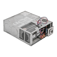
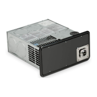
Furnaces
Sequence of operation for AC models:
1. The transformer receives 120 VAC, which it converts to 24 VAC for the operating circuitry.
2. The thermostat controls the operating circuit to the furnace by reacting to room temperature. When room
temperature is below the thermostat set-point, the contacts close to allow current to flow to the relay (the
relay can be either external or part of the ignition control board).
3. The relay receives 24 VAC and energizes a heater coil within the relay. With relay-on-the-board models,
timing is controlled through the microprocessor. A bi-metal disc is activated and closes the relay circuit
(17–20 seconds). On controls with a built-in relay, there is only a 1–2 second delay.
4. Once the relay circuit is closed, 120 VAC flows to the motor to operate the blower. One end of the motor
sha is for the blower wheel and the other end is for the combustion wheel.
5. Circulating air blows against the sail switch and closes the contacts, completing the circuit. The sail switch is a
safety device that ensures airflow before ignition.
6. The limit switch is a safety device that protects the furnace from overheating. The contacts in the limit switch open at
a given temperature setting, shutting off power to the electronic ignition system that controls the gas valve.
7. As power is applied to the electronic ignition circuit board, the system does the following:
a. A timing circuit allows the blower to purge the chamber (15–17 seconds).
b. The circuit board supplies current to the gas valve and causes it to open. There is an electrical switch in-line
to the valve that allows power to be manually shut-off from the valve. This switch must be on for the furnace
to operate. The switch may be separate or combined with the circuit breaker.
c. As the gas valve opens, the circuit board sends a high-voltage spark to the electrode at the burner. The
circuit board detects the presence of a flame.
– If the flame is not sensed aer approximately six seconds, the valve will close and the chamber will be
purged of any gas. Aer three tries for ignition, the control will lock out for one hour, unless power is
removed or the thermostat has cycled. Shutting off the main power will restart the cycle.
– If the system does not ignite and the thermostat remains closed, the contacts open to shut off power
from the valve, which shuts off the gas. The blower will remain on until the heater coil within the relay
cools and the relay opens to stop the current flow to the motor. With relay-on-the-board models,
timing is controlled through the microprocessor.
I
On newer controls, a diagnostic error code light has been added. By counting the flashes of the light, an
error code can be determined. See the Code Failure Table for code failure information.
Code Failure Table
Number of Flashes Diagnostic Information
1 Low Input Voltage
2 Ignition Failure
3 Open High Limit
4 Stuck APS (Sail Switch)
5 Module Fault
 Loading...