39
EN
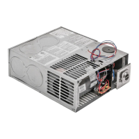
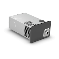
Furnaces
7.12 Servicing the gas valve
I
The burner head, electrode, and gas valve on the late model 79 series furnaces are individually accessible.
To service these same components on the late model 85 and 89 series, remove the complete assembly.
Perform the steps in Accessing the furnace components (on page 30) before proceeding with service.
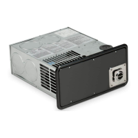
Testing the Ohms
40
Gas Valve
(Newer Model) (Older Model)
Older Models
➤ Using a Volt-Ohm Meter, measure the resistance on
the solenoid coil:
– Make sure the coils are isolated and
disconnected from the power and ground
sources.
– Place one meter lead on each coil terminal on
one of the solenoids.
– Confirm the resistance is between 30 Ohms
and 50 Ohms.
– Repeat the steps for the second solenoid.
Newer Models
➤ Using a Volt-Ohm Meter, measure the resistance on
the solenoid coil:
– Disconnect the positive terminal from the
power source.
– Disconnect the negative terminal from the
ground source.
– Make sure the coils are not isolated.
– Place one meter lead on the positive terminal.
– Place one lead on the negative terminal.
– Confirm the resistance is between 15 Ohms
and 25 Ohms.
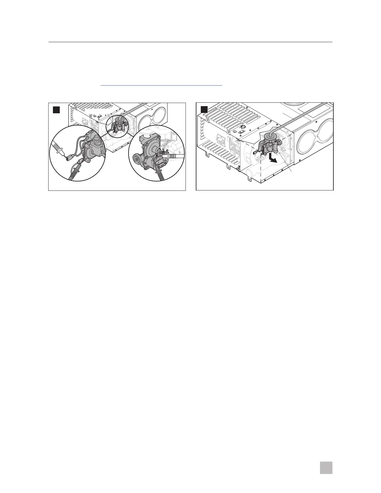
Adjust the Gas Supply Line
41
Gas Valve
Gas Line
I
Adjustment of the gas supply line is a solution
when the furnace lights and goes out
repeatedly, but does not enter lockout. It can
also occur during a pre-delivery inspection
(PDI) or the first time the unit is used in colder
weather. Mainly, this solution is necessary for
the AF Series furnaces.
➤ Locate the gas supply line for the furnace.
➤ When the furnace ignites, gently apply pressure to
the supply line to move it down and to the right in
very small increments.
➤ Continue to adjust the supply line until the furnace
remains lit aer ignition.
 Loading...