Form No. 30101_A 04/18 | ©2018 Dometic Corporation
HEATING
FURNACES
EN
Limit Switch Wire Rework
Service Bulletin
USA & Canada
Service Oce
Dometic Corporation
1120 North Main Street
Elkhart, IN 46514
Service Center & Dealer Locations
Visit:
www.dometic.com
Read these instructions carefully.
Furnace Model Serial Number Range Field Kit Number Kit Materials
AFS, AFM, DFS, DFM 73985322 – 81099541 31389
(1) Fiberglass Sleeve:
7” (length) x 1.5” (diameter)
1 SLEEVE INSTALLATION
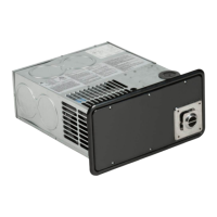
This x applies to all small and medium DF and AF door and less door furnace units.
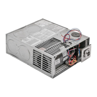
1.1 Examining the limit switch wires
Exhaust
Vent Area
1
Vent
Assembly
Limit
Switch
Screw
➤ Remove the vent assembly, and using a ashlight,
look through the opening in the vent cover to
inspect the exhaust vent area.
➤ Visually examine the limit switch wires for evidence
of the following conditions:
– Wires laying on the exhaust vent tube
– Melting at any point along the length of the wire
➤ If either condition exists, contact the Dometic
Technical Service department to obtain
authorization for removal of the furnace for
replacement, prior to repairing any wires or
continuing with this eld repair.
➤ If no damage is present, proceed with this eld
repair.
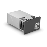
1.2 Placing the sleeve on a DF/AF unit
2
7" Fiberglass
Sleeve
7" Fiberglass
Sleeve
Vent Assembly
Exhaust
Extension
AF Placement
DF Placement
➤ Install the berglass sleeve:
– For DF units: slide the berglass sleeve over
the exhaust extension.
– For AF units: slide the berglass sleeve over
the vent assembly.
➤ Re-install the vent assembly.
 Loading...