Kits Purpose:
1. New wiring allows blower to be controlled thru ignition control instead of relay in furnace.
2. Wiring allows ignition control to give error codes listed on Diagnostic Sticker.
For ignition control installation refer to instructions supplied with control. These instructions only cover wiring for new ignition control P/N 33488
(CAT. NO. 35-535911-113) to do the above operations.
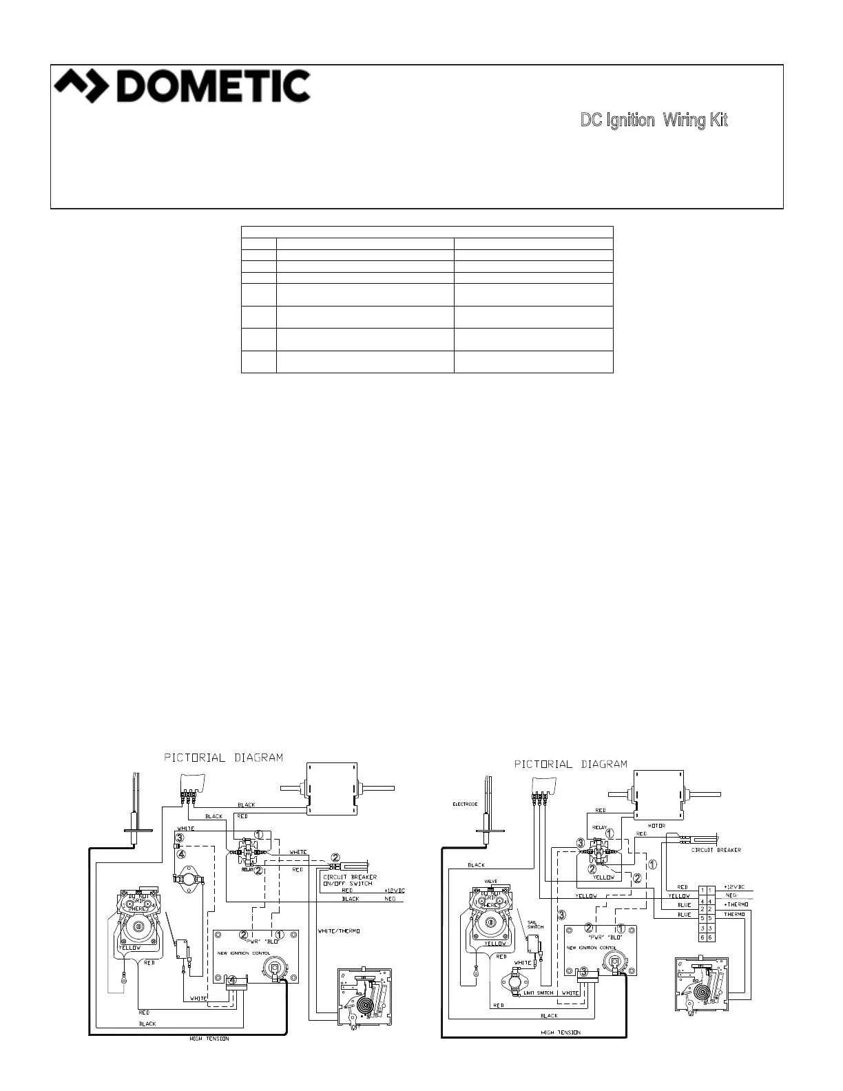
Wiring Instructions for 79/80-I & 7980-II MODELS
1. Remove red or orange motor wire from relay and connect to terminal marked “BLO” on new ignition control.
2. Discard red wire between relay and circuit breaker. Replace with red wire assembly from kit that has 3/16” F X 1/4" terminals; connect to
circuit breaker and terminal marked “PWR” on new control.
3. Connect fold over splice on white wire between limit switch and relay.
4. Connect blue wire assembly from kit to splice and insert into #2 location on edge connector (next to white wire) that goes onto ignition
control. Insert pin till it locks into locations.
5. Apply Diagnostic sticker to a visible location on face of Ignition bracket.
6. Use wire tie supplied to hold wires in position.
Wiring Instructions for 85-II, III, IV & 89-II & III Models
1. Remove red motor wire from relay, using red wire from kit with 1/4“ M X 1/4” F terminals connect to red motor wire and terminal marked
“BLO” on new control.
2. Remove red wire from other side of relay using red wire from kit with 1/4” M X 3/16” F terminals connect to red wire from relay and to
terminal marked “PWR” on new control.
3. Remove blue wire from relay and connect to blue wire from kit with 1/4” M X Contact Pin terminals. Connect to blue wire from relay and to
#2 location on edge connector on ignition control. (Next to blue or white wire) Insert pin till it locks in location.
4. Apply Diagnostic sticker to a visible location back of blower housing.
5. Use wire tie supplied in kit to hold wiring in position.
KIT INCLUDES:
QTY. COMPONENTS OF KIT MODELS USED ON
1
WIRE TIE
ALL MODELS
1
DIAGNOSTIC CODE STICKER
ALL MODELS
1
FOLD OVER SPLICER
79/80 MODELS ONLY
1
BLUE WIRE ASSEMBLY 1/4” M X CONTACT PIN
ALL MODELS
1
RED WIRE ASSEMBLY 1/4” F-90° X 3/16”
79/80 & 89 MODELS ONLY
1
RED F-90° 1/4” F-90° X 1/4” M WIRE ASSEMBLY
ALL MODELS
1
RED WIRE ASSEMBLY 1/4” M X 3/16” F-90°
79/80 & 85 MODELS ONLY
7900-I&II 8012-I&II DC WIRING
8500-II,III & IV 8900-II & III DC WIRING
LITERATURE NUMBER MPD 31294
DC Ignition Wiring Kit
• Effective 9/16
DOMETIC CORPORATION
1120 North Main Street, Elkhart, IN 46514
PHONE: 1-866-869-3118
INTERNET: WWW.EDOMETIC.COM
EMAIL: CUSTOMERSUPPORTCENTER@DOMETIC.COM
 Loading...