17
INSTALLATION
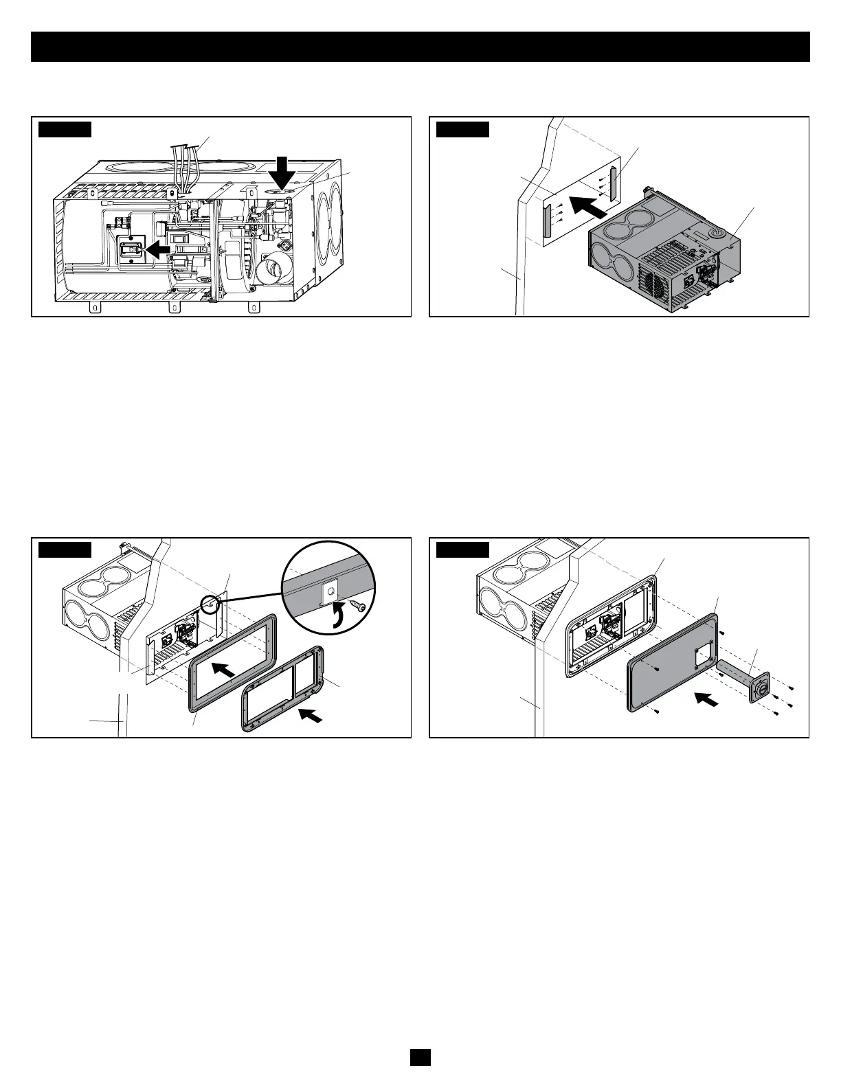
B. Installing The Furnace Using A Flush Door Option
STEP1
Gas
Connection
Electrical Connection
Flush-mounted door systems require the Furnace to be
installed on a 1" high platform, so the door cutout is level
with the floor surface. Otherwise, the side wall must be
routed out across the bottom to the depth of the bezel, to
create a pocket area. The flush door option requires 1/2"
radius corners.
• Place the Furnace through the cutout.
• Connect the electrical wiring. Refer to “H. Connecting The
Electrical” on page 22.
• Connect the gas line to the valve. Refer to “F. Connecting
The Gas” on page 20.
STEP2
Furnace
Flush Mounting Brackets
RV Wall
Recessed Side
Wall Cutout
• Use three screws (not included) on each side of the Furnace
to secure the flush mounting brackets to the wall. Leave
5/16" of space from the bracket to the outside of the wall.
• Apply RTV sealant or butyl tape to the back of the bezel
and the back of the flanges on the recess pan, where it will
overlap with the wall.
• Pull the front edge of the Furnace out of the wall
approximately 2".
STEP3
RV Wall
Recess Pan
Flush Mounting
Bracket
Bezel
Recessed
Side Wall
Cutout
• Slide the recess pan over the Furnace and place the bezel
on the six mounting tabs.
• Push the recess pan and bezel forward until the six casing
tabs move through the slots in the bezel.
• Bend the casing tabs to the outside of the bezel.
• Align the top three holes on the bezel with the holes in the
recess pan, then place six (three on the top and three on
the bottom) #6 or #8 x1/2" Pan Head Type AB screws, or
self-drilling screws, (not provided) into the top and bottom
holes on the bezel. Tighten the screws to attach the bezel
to the recess pan.
• Secure the Furnace using six (three per side) #6 or #8 x1/2"
Pan Head Type AB screws, or self-drilling screws, (not
provided) placed through the bezel, the recess pan, and
into the flush mounting brackets. Remove excess sealant.
Do NOT deform the bezel during placement. The bezel
must fit tightly to maintain an airtight seal.
STEP4
RV Wall
Door
Vent
Assembly
Bezel
• Secure the door using four #6-19x3/8" thread-forming
screws for plastic (not provided). The door should be flush
with the RV wall.
• Insert the vent assembly (provided) through the hole in the
door, making sure the vent assembly goes into the chamber
tube with the Dometic text aligned at the TOP.
• Secure the vent assembly to the door using four stainless
steel exhaust screws (provided with the door).
• To secure the Furnace to the floor of the RV, proceed to
“D. Installing The Mounting Brackets” on page 19.