10
v
English
L-2086 Installation
Manifolds
If a pump is serving multiple units, then a seawater manifold
will be needed to supply water to all units. This can be as
simple as a TEE for 2 units, or a custom made manifold for up
to 7 or 8 units.
It is very important to consider manifold orientation so that all
air conditioning units get the proper ow of water. See Figure
10 for manifold information.
A manifold can also be used on the outlets of the air condition
-
ing units when using a single overboard discharge.
Overboard Discharge
The overboard tting should be located between 1 to 2 inches
(25 - 50 mm) above the water line. This is to facilitate visual
conrmation of water ow, but also close enough to the water
to minimize splashing noise.
If the overboard tting must be installed below the heeled water
line, then a valve must be installed per ABYC standards.
Seawater Piping
• Only use reinforced marine grade hose or other suitable
piping (PVC, CPVC, Cupronickle, or Stainless steel).
• Double clamp all hose connections.
• Use only plastic, bronze, or stainless steel ttings (do not
use brass).
• Avoid loops or dips in the hose runs.
• Make sure enough hose is used to allow future removal of
components.
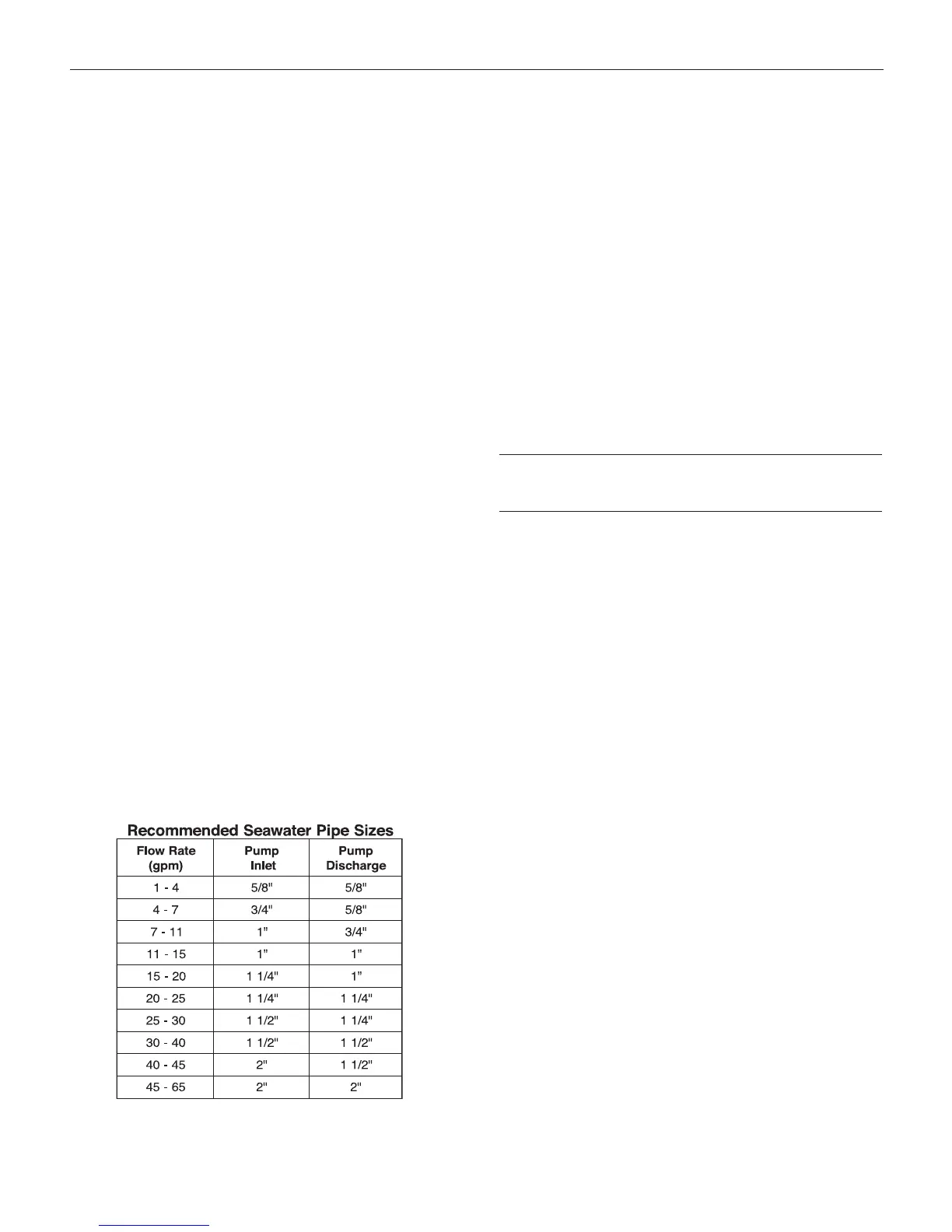
• Use the correct size hose, ttings, and components. See
the table below for proper seawater sizing. Note that the
pump inlet piping (including through-hull and strainer) may
need to be larger than the outlet pipe size. Do not use
pump connections to determine hose size.
• The “Pump Inlet” recommended pipe size includes all
ttings and hose (through-hull, seacock, strainer, etc.) up to
the pump inlet connection. The “Pump Discharge” includes
all piping/hose and ttings from the pump to the air condi
-
tioning unit or manifold, and to the overboard discharge.
• Use larger hose when the run is longer than 16 feet (5m).
Bonding
Bond all metallic parts (through-hull ttings, valves, strainer,
manifolds, etc.) that are in contact with seawater to the vessel’s
bonding system in accordance with ABYC standards E-8 and
E-9. Items should only be bonded or grounded once. If an item
is in contact with an electrically grounded part (pump head or
seawater condenser) then it should not be bonded again.
Installing The Air Distribution
System
The following instructions apply to both self-contained units
and remote condensing systems, except as noted. Refer to
Figure 11 for proper grill and duct sizes.
Return Air Grill (RA Grills)
The return air grill should be located so there is unobstructed
airow to the unit’s evaporator coils. Installing ducting between
the return air grill and the air conditioning unit is not normally
necessary and should be avoided. The grill may be located on
a side opposite the evaporator coil so long as airow to the coil
is unobstructed.
An air lter must be used to prevent the evaporator coil from
collecting dirt and lint. The lter can be located at the evap
-
orator coil or at the grill. Only one lter should be used. Most
self-cont
ained units and cooling units are supplied with an air
lter, but if the lter is not easily accessible, use a lter on the
return air grill.
Ducts
Insulated exible ducting or built-in ducting may be used to
route air from the blower to the discharge grill. Note that blow
through cooling units are installed directly behind the discharge
grill, and ducts are unnecessary. Likewise, with some overhead
cooling/heating units, air is discharged directly into the com
-
partment without ducts.
Ducting Guidelines
Secure duct to blower or transition box (plenum) with screws
and duct tape. When using insulated exible ducting, make
sure inner duct is secured and sealed to adapter before pulling
insulation over connection.
 Loading...