8
5. Plan ush switch panel location so that electrical connections
and wires cannot get wet.
6. Use MasterFlush 8100 series toilet wall switch template to
mark location of fastener and access holes for wall switch
panel. Drill 2.75 in. (70 mm) diameter hole (g.
9
).
7. With electrical power off, route 12-gauge or larger stranded
copper wire (according ABYC recommendations) from circuit
breaker or fuse to wall switch, and from wall switch to toilet.
Connect wires to appropriate leads attached to back of wall
switch panel with crimp-style wire connectors. (For complete
wiring options, refer to wiring diagrams (pp. 11-12).
8. Fasten wall switch panel to wall (g.
9
).
9. Route wall switch panel wiring to toilet through
access hole in oor. Route ground connection
wire to toilet. (Provide extra wiring at toilet to
easily remove toilet from mounting brackets for
future maintenance or service.) Make nal wiring
connections.
10. Route water supply and discharge plumbing to
toilet according to system requirements (Section
4.2). Provide extra water supply and discharge
hose lengths to assure easy connection to toilet
(g.
13
, page 9).
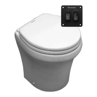
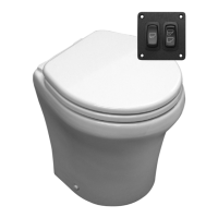
Dometic 8100 Series MasterFlush ToiletInstallation
Caution! Hazard of Flooding
If toilet uses raw water for ushing at ANY time, a raw water pump controlled by an automatically operat-
ing demand switch MUST NOT be installed. If the onboard water valve or any plumbing connections
were to leak, the automatically operated pump would start and could ood the boat. Failure to comply
with this warning can cause loss of property and life.
5.3 Toilet system with through-the-floor connections
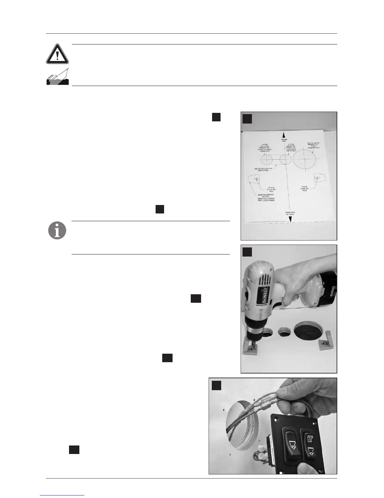
1. Place oor mounting template in desired location (g.
7
).
For optimal user comfort, make sure walls or other interior
xtures are at least 11 in. (279 mm) away from centerline of
template.
2. Center punch all holes and mounting bracket corners
through template.
3. Remove template from oor. Drill all access and fastener
holes as indicated on template. DO NOT drill mounting
bracket corners.
4. With long hex-head screws from toilet oor bracket kit,
fasten oor brackets with 3/8 in. (10 mm) socket wrench,
using corner marks as guides (g.
8
).
7
8
9
Note
Do not completely tighten hex-head screws to oor – allow
brackets to slightly slide. Brackets will tighten when fastening
toilet to brackets.
 Loading...