9
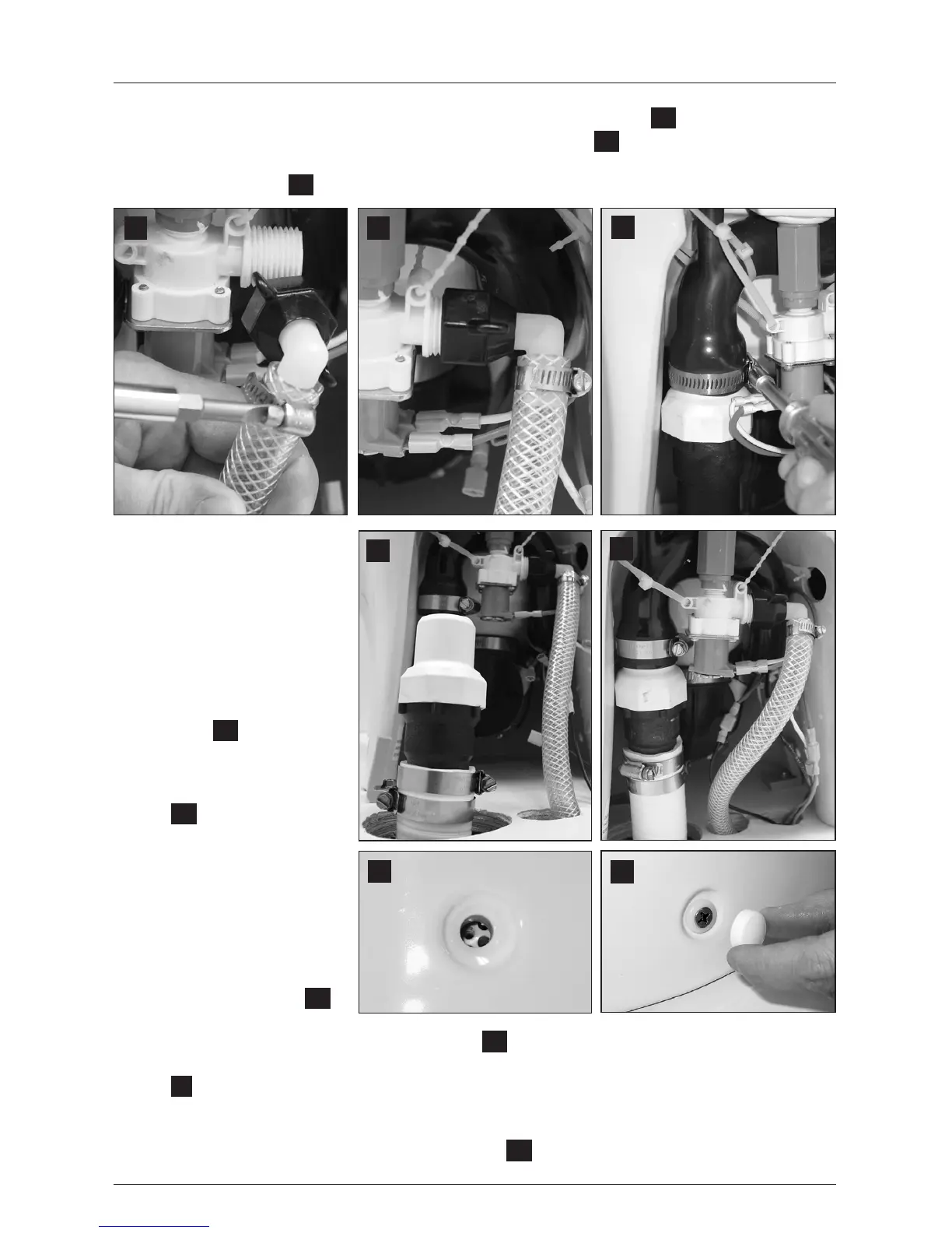
11. Connect water valve adapter to exible water line with hose clamp (g.
10
).
12. Securely connect water valve adapter to water valve tting (g.
11
).
13. Loosen band clamp on discharge loop outlet and remove discharge adapter tting/hose
tting assembly (g.
12
).
14. Lubricate discharge tting
assembly and inside end of
discharge hose with liquid
dishwashing soap. Push dis-
charge tting assembly into
discharge hose and connect
with two hose clamps. Be
sure to position hose clamp
screws 180° apart from each
other (g.
13
). Place toilet
near access holes.
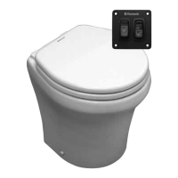
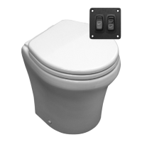
15. Connect ush switch panel
wires to toilet wires
(g.
14
) according to appro-
priate wiring diagram (pp. 11-
12). Connect ground wires
from toilet as indicated.
16. Position toilet over oor
brackets and tilt toilet up
from back. Push discharge
assembly tting and hose up
into discharge loop outlet,
and tighten clamp (g.
14
).
17. Lower toilet down so that
oor brackets show through fastener holes (g.
15
).
18. Turn on water supply and electrical power to toilet, and check for leaks. Press “Flush” switch
(g.
4
1, page 2). If leak occurs, tighten connection.
19. Insert plastic adapters from Floor Bracket Kit into fastener holes. Fasten toilet to brackets with
short screws provided in kit.
20. Cover oor bracket screws with plastic covers (g.
16
).
Dometic 8100 Series MasterFlush Toilet Installation
15
16
11
10
12
13
14
 Loading...