10
Dometic 8700 Series MasterFlush ToiletInstallation
5.4 Toilet system with flush handle and through-the-floor connections
- all applications
1. Follow steps 1-3 in Section 5.3.
2. Plan electronic control module and status panel locations so that electrical connections can be
made with cables provided. Be sure module and wires cannot get wet.
3. Use Dometic wall switch template to mark location of fastener and access holes for DSS status
panel (g.
1
N
, p. 2). Drill wiring access hole, then fasten panel bracket to wall.
4. Route ush handle cable (g.
1
O
, p. 2) from ush handle cable on control module (g.
1
F,
p. 2) to toilet location, and route ethernet cable (g.
1
E, p. 2) to DSS status panel location.
(If using status panel other than Dometic DSS panel, route orange connector end of Dometic
ush handle cable (g.
1
O
, p. 2) through access hole at toilet location. Route other section of
cable through status panel access hole and connect to panel wires. Attach status panel to wall.)
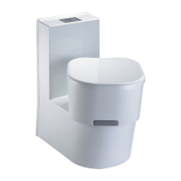
5. Install control module in cool, dry location, then attach Dometic ush switch/status panel cable(s)
to control module (g.
18
).
6. With electrical power off, complete wiring connections to control module. Refer to wiring diagram
printed with parts list (packed separately).
7. Route 4-wire control module cable (g.
1
D
, p. 2) to toilet through access hole.
8. Route water supply and discharge plumbing to toilet according to system requirements (Section
4.2). Make sure to provide extra discharge hose length to assure easy connection to toilet
(g.
19
).
9. Follow steps 11-13 in Section 5.3 to connect discharge plumbing and 4-pin connector at toilet.
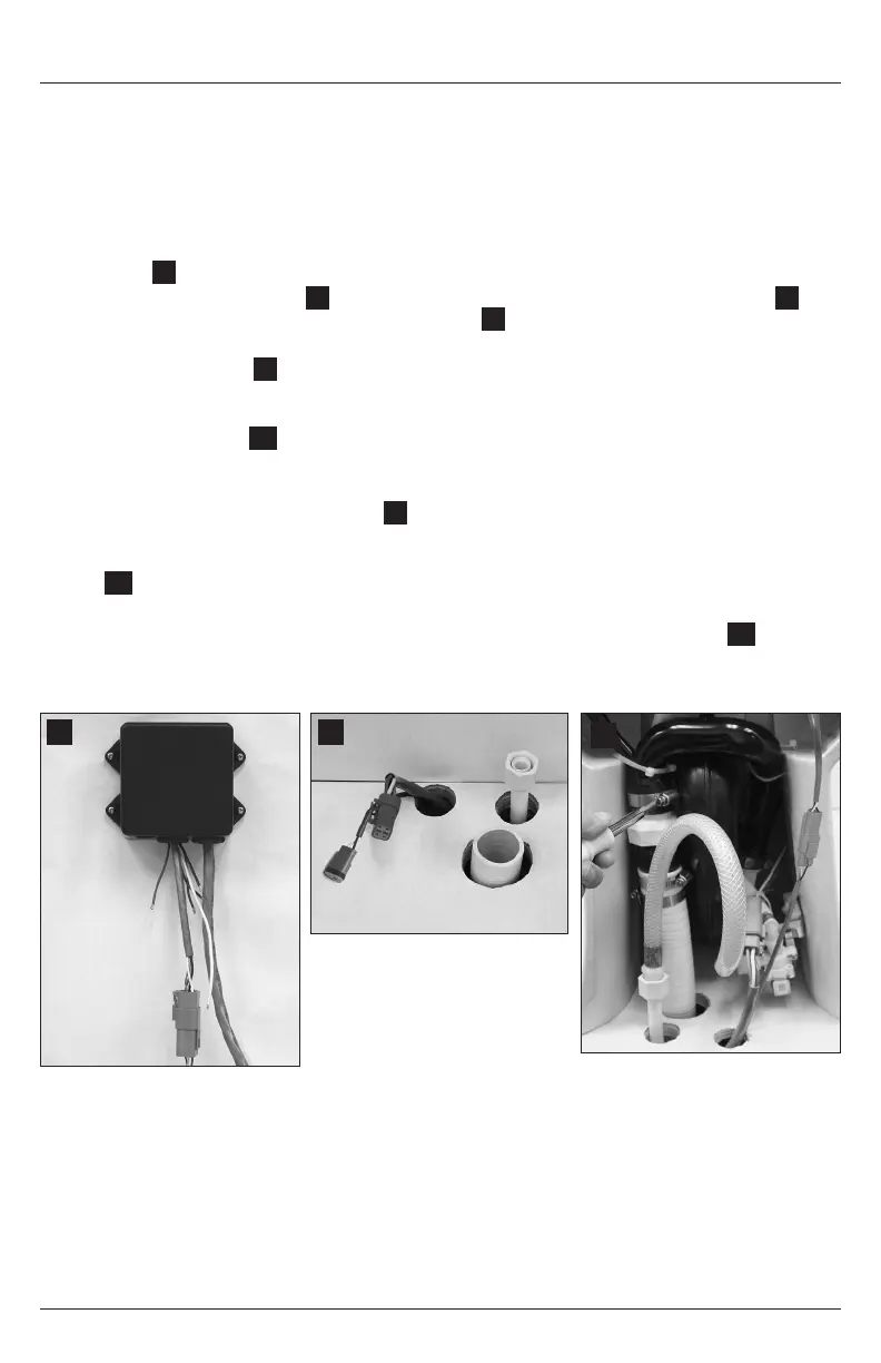
10. Connect 3-pin ush handle cable connector to 3-pin wire from control module (g.
20
).
11. Follow steps 14-17 from Section 5.3 to nish installation and testing. Press ush handle down
when testing operation and checking connections.
18
20
19