11
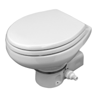
Dometic 8700 Series MasterFlush Toilet Installation
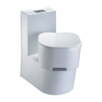
5.5 Toilet system with through-the-wall
connections
1. To route wiring and plumbing connections through the wall, use
oor template to locate the vertical centerline of each hole.
2. Place toilet in proper position and mark horizontal centerlines
(g.
21
).
3. Drill holes sizes as indicated on template.
4. Route wiring and plumbing through holes, then follow toilet
installation instructions beginning at Section 5.3 or Section 5.4,
step 4.
21
6 RV installation appendix
CONVERSION TABLE
Wire – AWG to mm
2
Feet to Meters
AWG 14 12 10 Ft 10 15 20 30 50
mm
2
2.5 4.0 6.0 M 3.1 4.6 6.1 9.2 15.2
Wire size per length of run* 0-15 ft. 16-30 ft. 31-50 ft.
12 volts DC #14 #12 #10
* Distance from circuit breaker to electronic control module.
WIRE SIZING CHART
When installing a Dometic macerator toilet in a recreation vehicle, please use the following wiring
information.
Installation notes
• Each toilet must have its own circuit breaker or fuse.
• Wire sizes must be appropriate for the installation. All other installation factors must be in accordance
with ISO electrical standards.
• Always use stranded copper wire (preferably tinned).
• Always use crimp-type wire connections. Do not use wire nuts (they corrode).
Warning!
Hazard of Shock or Fire: Always use recommended fuse, circuit breaker and wire size.
Failure to do so can cause the loss of property and life.
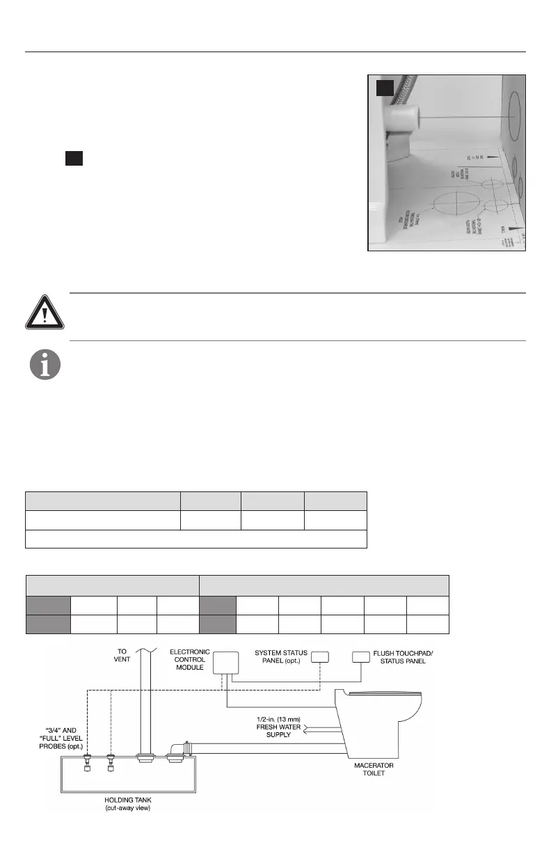
Wiring / Electronic Control Module Connections