Do you have a question about the Dometic Optimus EPS and is the answer not in the manual?
Symbols used to alert to potential hazards. Safety alerts and instructions.
Safety information for operating a boat with Optimus EPS. General, before use, during use, after use.
Warnings and guidelines for installers before, during, and after installation.
Reproduction of the safety decal on the electric actuator with warnings and instructions.
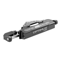
Describes the electric steering actuator and integrated SCU, a key system component.
Explains the function of the electronic helm, which converts wheel movement to digital messages.
Describes the CANtrak display's functions for system status, faults, and settings.
Explains CAN networks (CANI, CAN2, CAN3) used for system communication.
Describes the Optimus 360 joystick control system for enhanced maneuverability.
Steps to take before operating the boat for the first time, including familiarization and inspection.
Procedure for inspecting the steering system and engine controls before each use.
Steps to check for interference between components during steering and tilt operations.
General guidelines and warnings for operating the Optimus EPS system.
Recommendations for the initial sea trial and familiarization with the system.
Overview of the CANtrak display's purpose and functions, including status and fault handling.
Explanation of the buttons and navigation within the CANtrak display menu.
Diagram showing the progression of screens on the CANtrak display for normal steering mode.
Description of the main operating (Run) screen on the CANtrak display.
Access to actuator calibration and move functions for maintenance purposes.
Adjusting steering effort and helm turns parameters for personalized steering.
How steering parameters adjust automatically based on boat speed for optimal handling.
How to adjust the brightness of the CANtrak display for different lighting conditions.
How the EPS system interfaces with and operates with autopilot systems.
Introduction to the Optimus 360 joystick control system for enhanced maneuverability.
Basic operations, handle motion, and buttons of the joystick controller.
Explanation of LED states on the Take Command button indicating joystick status.
Primary operational modes (Forward/Reverse, Sideways, Rotation) of the joystick.
Diagrams illustrating primary joystick motions: Forward/Reverse and Sideways.
Advice and best practices for using the joystick controller effectively for precise control.
Step-by-step examples of common joystick maneuvers for docking and approach.
Further examples of joystick maneuvers for docking, including correcting for wind or current.
Final steps in joystick docking examples, including entering a slip and stopping.
Procedures to switch from joystick control back to conventional steering.
Definitions of Danger, Warning, and Caution faults and their impact on system performance.
How the system notifies users of faults via buzzer and CANtrak display warnings.
Actions to take when a critical (danger) fault occurs, often requiring limping home.
How to use 'Limp Home' mode to safely return to port during a fault condition.
Instructions for Limp Home Mode 1 (no steering) and Mode 2 (one actuator disabled).
Procedure for manually repositioning a steering actuator during a fault.
How to handle non-critical (warning) faults and resume normal operation.
Steps to take if the CANtrak display is not working or is lost.
Preparations and information needed before beginning the installation process.
Overview of available electric actuator configurations for different engine applications.
Considerations for actuator harness routing, slack, and minimum bend radius.
Step-by-step procedure for physically installing the electric actuator onto the engine.
Procedure for installing the ground strap on the electric actuator to prevent corrosion.
Details on selecting and planning the actuator harness, including styles and lengths.
Procedure for installing the harness through the transom using a bulkhead fitting.
Methods for bundling and protecting the actuator harness for a tidy and reliable installation.
Steps for connecting the actuator harness to the electric actuator connector.
Overview of the four available electronic helm styles and their part numbers.
Planning for routing CAN1 harnesses and ensuring system integrity for helm installation.
General procedure for installing the electronic helm, including grounding.
Installation diagram and ground strap procedure for the Front Mount Helm (EH1510/EH1512).
Installation diagram and ground strap procedure for the Sport Plus Tilt Helm (EH1530/EH1532).
Installation diagram and ground strap procedure for the Classic Tilt Helm (EH1550/EH1552).
Installation diagram and ground strap procedure for the Rear Mount Helm (EH1570/EH1572).
Considerations for planning the installation of the Color CANtrak Display.
Guidelines for mounting the CANtrak display for optimal visibility and connectivity.
Overview of all system electrical connections made from the actuator harness bundle.
Details on making the 12V power connections for the system, adhering to ABYC standards.
Typical source connections and circuit protection requirements for power supply.
Battery connection considerations for multi-engine setups to prevent battery drain.
Specific steps for making 12V power connections, including breaker installation and wire sizing.
How to connect the CAN1 network for helms and CANtrak displays, emphasizing safety-critical nature.
Planning for CAN1 harness lengths, extensions, and connections for system integrity.
Diagram for single-engine, single-station CAN1 connection using extension harnesses.
Diagram for single-engine, dual-station CAN1 connection using wye and extension harnesses.
Diagram for multi-engine, dual-station CAN1 connection using CAN1 Hub.
Diagram for multi-engine, dual-station CAN1 connection using extension and wye harnesses.
Harness routing, connector installation, and securing for the CAN1 network.
How to connect the CAN2 network for displays and approved third-party autopilots.
Planning and building the CAN2 network backbone using tees and extension harnesses.
Installation of network tees, harnesses, and terminating resistors for the CAN2 network.
Connecting the CAN3 network for engine RPM data and broadcasting rudder position.
Connecting the ignition-sensing wire for system wake-up signal.
Application-specific instructions for connecting ignition sensing wires for single and multi-engine systems.
Steps for initial system power-up, accessing the dealer menu, and handling initial warnings.
Steps for the initial system setup, including selecting system type and steering type.
Choosing the correct system type (e.g., Optimus EPS) for proper system configuration.
Selecting the appropriate steering type (e.g., Outboard Optimus Electric) for the installation.
Configuring the quantity of devices on the CAN network for system recognition.
Instancing devices (port/stbd, main/2nd station) correctly to teach the system device roles.
Selecting the source for engine RPM data, defaulting to CAN3.
Tasks related to setting up the steering system parameters and calibration.
Adjusting engine wedge angle for optimal performance, particularly for joystick control.
Procedure for calibrating the steering actuators to teach the SCU end-of-travel points.
Adjusting helm sensitivity for more responsive steering at neutral rudder position.
Performing final interference checks after setup is complete.
Using the Move Steering function for diagnostics or service tasks.
Routine maintenance schedules for ensuring safe and reliable service from the EPS system.
Maintenance tasks for the boat owner/operator before and after use.
Maintenance tasks for qualified mechanics at 20-hour and 100-hour intervals.
Common faults, their causes, and solutions for Optimus EPS system issues.
Mounting template for the Front Mount Helm (EH1510/EH1512).
Mounting template for the Sport Plus Tilt Helm (EH1530/EH1532).
Mounting template for the Classic Tilt Helm (EH1550/EH1552).
Mounting template for the Rear Mount Helm (EH1570/EH1572).
Mounting template for the Color CANtrak Display.
Mounting template for the bulkhead fitting used for harness installation.
Recommended maximum torque values for reusable dry bolts used in installation.
Key technical specifications for the Optimus EPS system, including voltage and current draw.
Details of the limited warranty for SeaStar Solutions products.
Procedure for returning products for warranty claims or service.
Contact information for technical support, including phone and email.
| Brand | Dometic |
|---|---|
| Model | Optimus EPS |
| Category | Marine Equipment |
| Language | English |